June 15, 2005 6815854H01-A
3-70 Theory of Operation: Controller Section
3.14.7 Serial Communications on the External Bus (SB9600)
The SB9600 bus is an asynchronous serial communication bus using a Motorola-proprietary
protocol. It provides a means for the microcontroller within the Patriot IC (U100) to communicate with
other hardware devices. In the radio, it communicates with hardware accessories connected to the
accessory connector. Serial communications on this external bus uses three of the four SB9600
lines: BUS+ (J0402-3), BUS- (J0402-5), and BUSY (J0402-6) data lines originating from the
microcontroller's secondary UART.
These three lines are bidirectional; therefore, numerous devices can be in parallel on the bus. All
devices monitor the bus while data is being transmitted at a 9600-baud rate.
The microcontroller sends the data transmission from UARTB, onto the bus at 0-V and 2.85-V levels.
Next, the software sets microcontroller SB96_RS232_EN to a logic HIGH. Buffers (U0602 and
U0603) are now powered and the data is changed to the SB9600 format via pull-up and pull-down
logic circuitry. SB96_RS232_EN also sets the data MUX (U0606) to route the new SB9600-
formatted data to the correct lines at the rear of the radio (J0402-3, J0402-4, J0402-5, and J0402-6).
Since SB96_RS232_EN is kept HIGH as the default state, the UARTB default function is for SB9600
data traffic only.
When the microcontroller sends data onto the bus, the microcontroller monitors the transmitted data
as a collision-detection measure. If a collision is detected as a result of receiving a different data
pattern, the microcontroller will stop transmission and try again; that is, when the RESET line
(J0402-4) is used.
Data bus drivers for the BUS+ and BUS- lines are differentially driven, having BUS- inverted from the
state of BUS+. The drivers are so designed that any of the devices on the bus can drive these lines
to their non-idle state without loading problems.
In a typical data transmission, the microcontroller examines the BUSY line. If the BUSY line is in the
idle state, the microcontroller sets the BUSY line HIGH, and then it transmits using BUS+ and BUS-.
At the end of the transmission, the microcontroller returns the BUSY line to idle.
The idle states for the SB9600 lines are: BUS+ = logic HIGH, BUS- = logic LOW, BUSY = logic LOW,
and RESET = logic LOW.
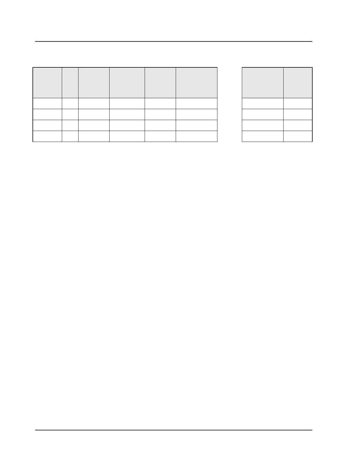
Table 3-12. Rear Connector Naming Scheme
Radio Pin
Direction
J2
Pin
No.
J2 Pin Name
Pin Alternate
Name
EIA-
Compatible
Name at
Rear Conn.
J2
P2 Rear
Accessory Cable
DB9 (Female) =
DCE Interface
DB9 (Male) Serial
Port Connector =
DTE Interface
Data
Device Pin
Direction
Output 4 UARTA_TX No Change TX_DCE TX_DCE = pin 2
<-->
pin 2 = RX_DTE Input
Input 5 UARTA_RX No Change RX_DCE RX_DCE = pin 3
<-->
pin 3 = TX_DTE Output
Output 10 UARTA_CTS Becomes RTS RTS_DCE RTS_DCE = pin 8
<-->
pin 8 = CTS_DTE Input
Input 11 UARTA_RTS Becomes CTS CTS_DCE CTS_DCE = pin 7
<-->
pin 7 = RTS_DTE Output
Note: Connecting to a computer = DTE device
TX to RX and RTS to CTS

 Loading...


