June 15, 2005 6815854H01-A
5-6 Troubleshooting Charts: Troubleshooting Tables
5.3.2 For UHF R2 Models
This section contains troubleshooting tables that can help you isolate a problem in your radio.
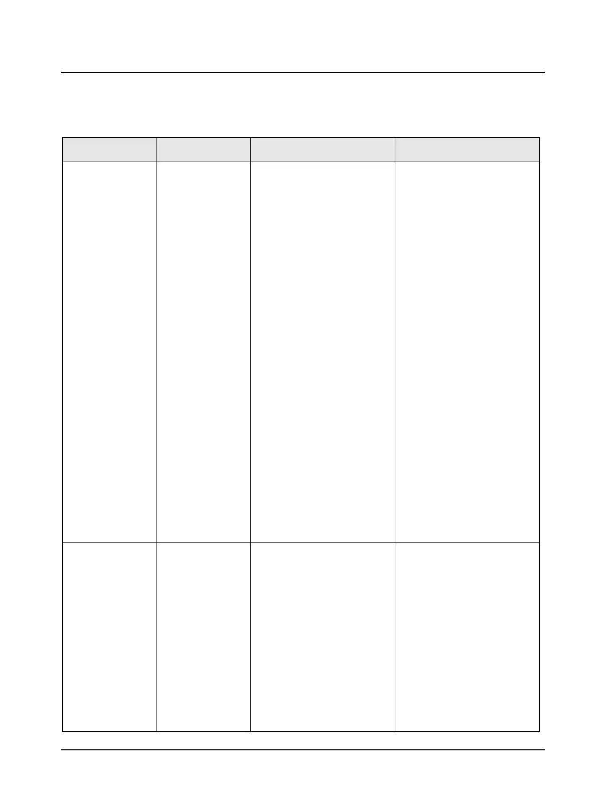
Table 5-3. XTL 1500 Troubleshooting Table (450-520 MHz)
Symptom Check Section Troubleshooting Procedure Component
No TX Modulation Controller Block With 80 mV rms, 1 kHz injected
to the MIC_HI line and CPS mic
gain level set to 0 (default),
check the following levels.
• 80 mVrms at TP0200, U0209-
4, J0401-57.
• 80 mV rms at TP0201.
• 2.5 Vdc at U0201-8.
• 80 mV rms at U0201-7,
U0201-7, TP0203.
• 36 mV rms at U0200-17.
• > 150 mV rms at U0900-1.
• > 150 mV rms at FL0900-5.
• > 150 mV rms at U0902-14
• > 150 mV rms at R6782
• Absence of signal may indicate
failure with U0209 (MUX), or
U0201 (Op-Amp)
• Absence of signal may indicate
failure with U0209 (MUX), or
U0201 (Op-Amp)
• Absence of DC bias may
indicate failure with U0201
(Op-Amp)
• Absence of signal may indicate
failure with U0202 (EPOT), or
U0201 (Op-Amp)
• Absence of signal may indicate
failure with U0200 (Codec)
• Absence of signal may indicate
failure with U0901 (Urchin),
U0900 (Modulation DAC), or
U0001 (Microprocessor Board)
• Absence of signal may indicate
failure with U0901 (Urchin), or
FL0900 (Filter)
• Absence of signal may indicate
failure with U0902 (MUX)
• Presence of signal may
indicate a aproblem in RF
section
Flex/Control Head Check that MIC_HI is getting to
controller at VR0412, VR0421,
C0438, C0207, C0234, or R0204
Absence of signal may indicate
failure with flex, control head,
VR0412
Radio Dead, No
Display, No LED
Backlighting
Blown Fuse Check fuse in red lead of power
cable (or green lead if used)
Absence of signal may indicate
failure with J0401, J0402,
VR0412, or VR0402
Controller Section • Check for IGNITION (if enabled
as required in CPS) at J0401-
27, 28
• Check for A+ at Q0503,
VR0950, J0401-19,21, or
TP0414
• Absence of signal may indicate
failure with J0401
• Absence of signal may indicate
failure with J0950, J0401 or
VR0950
Flex/Control Head Check for SW_B+ at J0401-
33,34, TP0413.
Check for all voltages in CH;
1.55V, 1.88V, 2.8V, 3.3V, 5V and
UNSW_VCC (3.0V).
Absence of signal may indicate
failure with flex, control head

 Loading...


