June 15, 2005 6815854H01-A
3-66 Theory of Operation: Controller Section
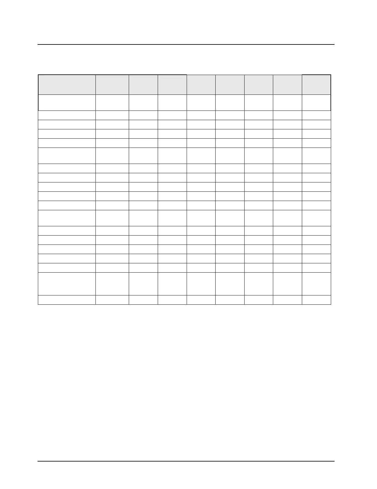
The various voltages used by the ICs on the main board are shown in Table 3-11.
3.14.3 Reset Circuits
The reset circuits consist of the power-on reset (POR*) circuit (Figure 3-45), SW_B+ sense circuit,
and SB9600 bus reset circuit. These circuits allow the microprocessor to recover from an unstable
condition, such as removing battery A+ from the radio while it is on, battery voltage too low, and
miscommunication to remote devices on the SB9600 bus, as well as generally monitoring the power
on/off condition.
Table 3-11. Integrated Circuits Voltages
Integrated Circuit UNSW5V SW 5V A+ 3.0 V 2.85 V
9.3 V_T
X
1.85 V 1.55 V
Patriot
Microprocessor
U100 U100 U100
Flash U102
SRAM U103
A/D U0953-28
D/A U0959-4
Modulation D/A U0900-3
FL0900-4
Urchin U0901
RS-232 XCVR U0305-16
USB XCVR U0304-7
Audio PA U0204-7
CODEC U200-6
Amplifiers, EPOTs U0201-4
U0202-3
555 Timer U0506-4
SB9600 MUX U606-16
Volume Pot U0206-7
32K Crystal Y0100-5
Modulation MUX U0902-16
Power Control U0956-4
U0957-4
U0960-4
Keyed 9.1 V Switch Q0952

 Loading...


