6815854H01-A June 15, 2005
Troubleshooting Charts: Flowcharts 5-45
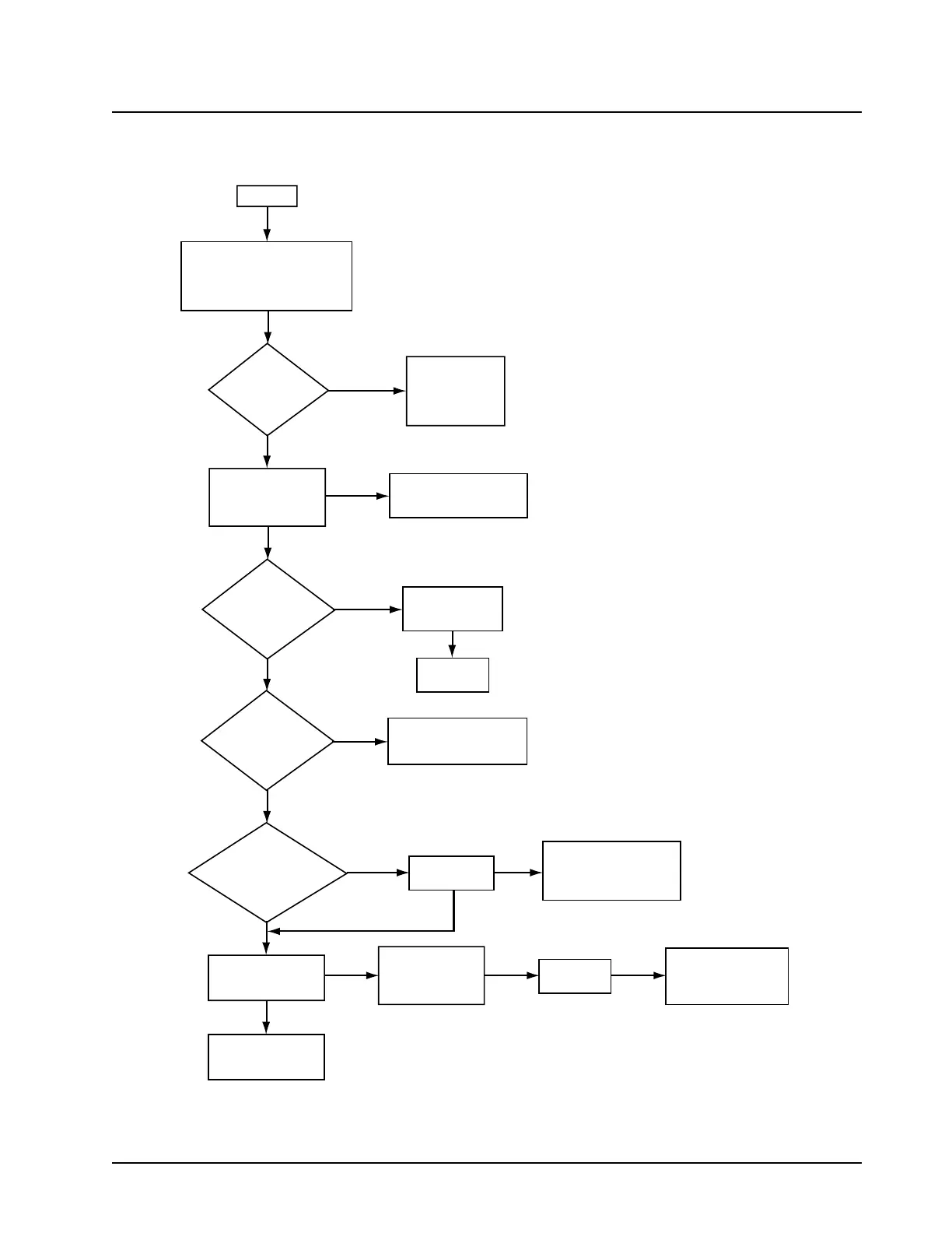
5.6.34 Poor RX Sensitivity or No RX Audio (700–800 MHz)—Part 2 of 2
Figure 5-34. Poor RX Sensitivity or No RX Audio (700–800 MHz)—Part 2 of 2
MAEPF-27874-O
1
Inject a standard FM test
signal into the antenna port.
Use a spectrum analyzer and
high-impedance RF probe to
measure the signal at TP6253.
<~1dB Loss
relative to Antenna
switch?
Check LNA Input
(U6250) Pin 3. RF
Level:<~2.5dB Loss
from TP6253
Check
LNA Output
TP6250. RF Level:
~16dB gain from
U6250 Pin
3?
Check
Mixer Input,
TP6251. RF Level:
<~2.5dB Loss from
TP6250?
Check
Mixer Output,
TP6252. Freq: 73.35MHz
RF Level: <~7db
Loss from
TP6251
RF Level at
TP6252<~7db
loss from TP6251
Go to IF Section
Troubleshooting
flowchart
3kHz FM Deviation
1kHz Audio tone
Amplitude: 47dBm
Check Output
Network (ON)
troubleshooting
flowchart of
Transceiver
Check bias
voltage at Pin 1
of U6250 for 5V
Replace
part
Check filter switching
table for proper voltages.
Visually inspect filters
Is Output Freq
at 73.35MHz?
Check RF level at
Mixer LO injection
port. (U6251
Pin 3 side 1)
Check Pin 3 on U6251
for correct LO frequency
(based on your
Receiving signal)
RF level
at ~14dBm
Check Receiver
VCO troubleshooting
flowchart
(LO injection section)
No
Yes
Yes
Yes
Yes
Yes
No
No
No
No
No
Check filter switching
table or proper voltages.
Visually inspect filters
No
_
_
_
_
Yes
Yes

 Loading...


