June 15, 2005 6815854H01-A
3-28 Theory of Operation: Receiver Back-End
3.11.4.1 Intermediate Frequency (IF) Filter
The XTL 1500 radio uses two leadless, surface-mount, two-pole, third-overtone, quartz crystal filters
(B6350, B6351) separated by a 20 dB gain IF amplifier. The filter is centered at 73.35 MHz. This
narrow-bandpass filter gives the radio its adjacent-channel and alternate-channel rejection
performance. Components L6350, L6351, L6352, L6353, C6351, C6352, C6353, C6355, C6356,
and C6357 are used as impedance-matching networks. Components L6355, R6354, R6352, R6353,
C6354, and R6350 are used for biasing and stabilizing the transistor Q6350. Component C6358
bypasses the DC supply. L6355 is an RF choke.
3.11.4.2 ABACUS III IC (U6000)
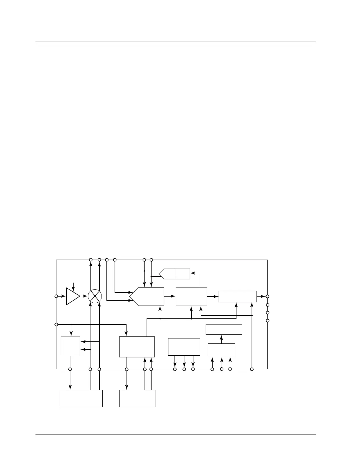
The receiver back-end is designed around the ABACUS III (AD9874 IF digitizing subsystem) IC and
its associated circuitry. The AD9874 (Figure 3-21) is a general-purpose, IF subsystem that digitizes a
low-level, 10–300 MHz IF input with a bandwidth up to 270 kHz. The signal chain of the AD9874
consists of a variable gain, low-noise amplifier, a mixer; a bandpass, sigma-delta, A/D converter; and
a decimation filter with programmable decimation factor. An automatic gain control (AGC) circuit
provides the AD9874 with 12 dB of continuous gain adjustment. The high dynamic range and
inherent anti-aliasing provided by the bandpass, sigma-delta converter allow the AD9874 to cope
with blocking signals 80 dB stronger than the desired signal. Auxiliary blocks include clock and LO
synthesizers, as well as an SPI port. Input signal RXIF is the 73.35 MHz IF from the IF filter in the
receiver front-end.
Components C6000, C6001, and L6000 match the input impedance from 50 ohms (IF Filter
terminating impedance) to the ABACUS III IC input IFIN. Formatted SSI (synchronous serial
interface) data is output to the Patriot microcontroller IC for DSP processing on ports FS, DOUTA,
and CLKOUT. Control logic is sent to the ABACUS III IC from the Patriot microcontroller via the SPI
lines (PC, PD, PE).
Figure 3-21. ABACUS III (AD9874) IC Functional Block Diagram from Data Sheet (700–800 MHz)
IFIN
FREF
-16dB
LNA
LO
Synth.
Sample Clock
Synthesizer
CLK VCO and
Loop Filter
LO VCOand
Loop Filter
Voltage
Reference
DAC AGC
ADC
Decimation
Filter
Formatting/SSI
Control Logic
f
CLK
= 13-26MHz
SPI
DOUTB
DOUTA
FS
CLKOUT
MXON
MXOP
IF2P
IF2N
GCP
GCN
LOP
IOUTL
LON
IOUTC
CLKP
CLKN
VREFP
VCM
VREFN
PC
PD
PE
SYNCB
MAEPF-27817-O
AD9874

 Loading...


