June 15, 2005 6815854H01-A
5-10 Troubleshooting Charts: Troubleshooting Test Points
5.4 Troubleshooting Test Points
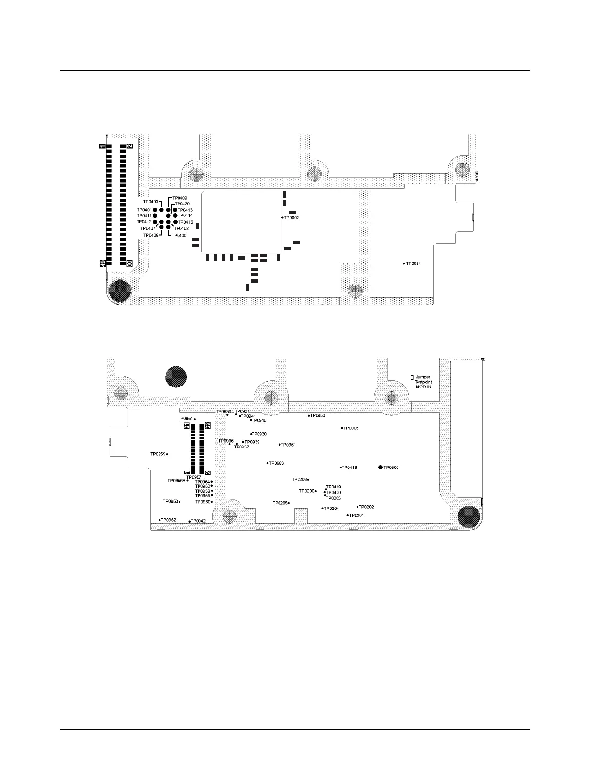
The following figures show the location of the main board test points for measuring voltages and
viewing waveforms.
Figure 5-1. Main Board Test Points—Top Side
Figure 5-2. Main Board Test Points—Bottom Side
5.5 Board ID Jumper Configuration
The following jumper table (Table 5-5 on page 5-11) is provided for troubleshooting and determining
what board revision you have. This can be helpful in the event a jumper was placed incorrectly or
was removed during a repair and the radio is not functioning correctly.
This table provides two types of information:
• RF band of the radio
• Overall revision of the main board and controller section
MAEPF-27802-O
ID7
ID6 ID5 ID3
ID4
ID2
ID1
ID0
MAEPF-27801-O

 Loading...


