June 15, 2005 6815854H01-A
3-20 Theory of Operation: Receiver Front-End
3.10.3 UHF Range 2 (450–520 MHz) Band
The receiver circuits primary duties are to detect, filter, amplify, and demodulate RF signals in the
presence of strong interfering noise and unintended signals. The receiver (see Figure 3-16) is
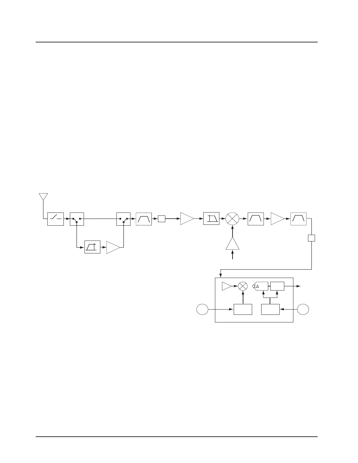
broken down into the following blocks:
• Front-end, which includes:
- High pass fIlter and first low-noise amplifier (LNA)
- Preselector filter
- Switchable 15 dB attenuator
- Second LNA
- Image Filter
- First mixer
• Back-end, which includes:
- Intermediate Frequency (IF)
- ABACUS III IC
Figure 3-16. Receiver Front-End and Back-End (UHF Range 2)
3.10.3.1 Highpass Filter and First Low-Noise Amplifier
The highpass filter and first low-noise amplifier (LNA) (11 dB gain) can be switched in and out of the
signal path by diode switches. When switched into the signal path, the sensitivity of the radio is
improved at the cost of degraded intermodulation performance. This can be necessary in fringe
areas when strong interference that can lead to intermodulation problems are not present and the
desired signal is weak.
The preamplifier version of the radio must be purchased to be able to control this option. If it has not
been purchased, the direct path created by the diode switches is the only one available, giving the
radio standard model performance with enhanced intermodulation rejection. Purchasing the
preamplifier option allows the user to select either mode with the CPS.
Ant. SW.
Harm. FLT
Pre-Amp
Switch
Pre-Amp
Switch
Mixer
Preselector
15 dB
Att.
Low Pass
Filter
RF Input
Crystal
24dBm
1st LO
Backend A/D Converter
SSI
Dec.
Filter
CLK
Synth.
LO
Synth.
2nd
LO
18MHz
CLK
IF Amp Crystal
109.65MHz
A
10 dB
Att.
450-520MHz
LNA
High Pass
Filter
LNA
ADC
ABACUS III IC
A

 Loading...


