Chapter 3 Theory of Operation
3.1 Control Head Board
This section provides a detailed circuit description of the XTL 1500 radio control head board for VHF/
UHF Range 1/UHF Range 2/700–800 MHz models. The control head board contains the following
major sections:
• Controller (page 3-2)
• Power Management (page 3-3)
• User Interface (page 3-7)
• GCAI Accessory Interface (page 3-7)
When reading the theory of operation, refer to your appropriate schematic and component location
diagrams located in “Chapter 7. Schematics, Component Location Diagrams, and Parts Lists”. This
detailed Theory of Operation will help isolate the problem. However, first use the ASTRO Digital
XTL 1500 VHF/UHF Range 1/UHF Range 2/700–800 MHz Mobile Radio Basic Service Manual
(6815853H01) to troubleshoot the problem to a particular board.
3.2 Control Head Board Major Sections
This section contains the control head board layouts for XTL 1500.
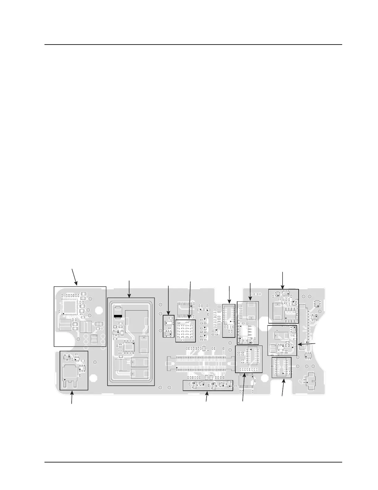
The illustrations (Figure 3-1 on page 3-1 to Figure 3-2 on page 3-2) identify the location of the major
sections of the control head board.
Figure 3-1. XTL 1500 Control Head Board Sections — Side 1
BATTERY_A+
C1026
C1027
C1028
C1031
C1032
C1034
C1035
C1038
C1039
C1040
C1200
C1201
C2100
C2101
C2102
C2103
C2104
C2105
C2200
C2201
C2202
C2204
C2205
C2206
C2207
C2208
C3101
C3102
C3103
C3104
C3107
C3200
C3201
C3202
C3203
C3204
C4201
C4203
C4204
C4205
C4206
C4207
C4208
C4209
C4210
C4211
C4212
C5000
C5001
C5002
C5003
C5004
C5005
C5006
C5007
C5008
C5009
C5010
C5011
C5012
C5013
C5014
C5015
C5016
C5017
C5018
D1000
D1001
D2200
D2201
E2100
E2101
E2102
GROUND_1
GROUND_2
GROUND_3
G2
G1
1
2
70
69
J5000
L2100
L2101
L2200
L2201
1
2
15
16
P2300
12
G1
G2
P3200
1
2
15
16
P4200
2
G1
G2
P4201
1
2
15
16
P4202
Q1000
Q1001
Q1002
4
5
8
Q2100
Q2101
Q2200
Q2201
3
2
1
Q2202
Q3100
Q3101
R1002
R1003
R1005
R1006
R1007
R1022
R1023
R1024
R1025
R1026
R1027
R1028
R1029
R1030
R1031
R1040
R1041
R1042
R1043
R1046
R1047
R1048
R1049
R1051
R1052
R1053
R1054
R1055
R1056
R1057
R1058
R1059
R1060
R1064
R1065
R1066
R1068
R1069
R1200
R1201
R1202
R1203
R1204
R1205
R1207
R1208
R1210
R1211
R1212
R1213
R1214
R1215
R1216
R1217
R2102
R2108
R2 111
R2112
R2115
R2116
R2123
R2129
R2130
R2131
R2132
R2133
R2134
R2139
R2140
R2141
R2200
R2201
R2202
R2203
R2204
R2205
R2206
R2207
R2208
R2209
R2210
R2211
R2212
R2213
R2214
R2215
R2216
R3102
R3116
R3117
R3118
R3119
R3120
R3121
R3212
R3213
R3214
R3215
R3216
R3217
R3218
R3219
R4204
R4205
R4207
R4208
R4210
R4211
R4212
R4213
R4214
R4215
R4216
R4217
R4218
R4219
R5000
R5001
R5002
R5003
SH2200
TP_1.55V
TP_1.88V
TP_2.8V
TP_3.3V
TP_5V_EN
TP_IGNiTION
TP_MUX_EN
TP_MUX_SEL
TP_ON_OFF_1
TP_ON_OFF_2
TP_PB1
TP_PB2
TP_PB5
TP_SW_5V
TP_UNSW_2.8V
TP_USB_DM
TP_USB_DP
TP_USB_VBUS
TP_VBUS_MODE_SEL
TP_VBUS_OC_DET
U1001
11
1
20
10
U1002
U1003
U1005 U1006
U1007
U1008
11
1
20
10
U1200
36
24
12
U2100
5
8
1
4
9
U2200
1
4
58
U2201
1
4
58
U3101
4
3
5
U3102
U3105
U3200
U3201
VBUS_SRC
VR2200
VR2201
VR2202
VR3200
VR3202
VR3203
TPS65012
PWR MGT IC
5V
SWITCHING
REGULATOR
FACTORY
BOOT
OMAP
CONFIG.
LCD CONN.
RX AUDIO
OP AMP
UNSW VCC
VOLUME
CONN.
AVR PROG
CONN.
VIPOUTs
USB 5V
CURRENT
LIMITER
SW_B+
CONTROLS

 Loading...


