6815854H01-A June 15, 2005
Theory of Operation: Power Management 3-5
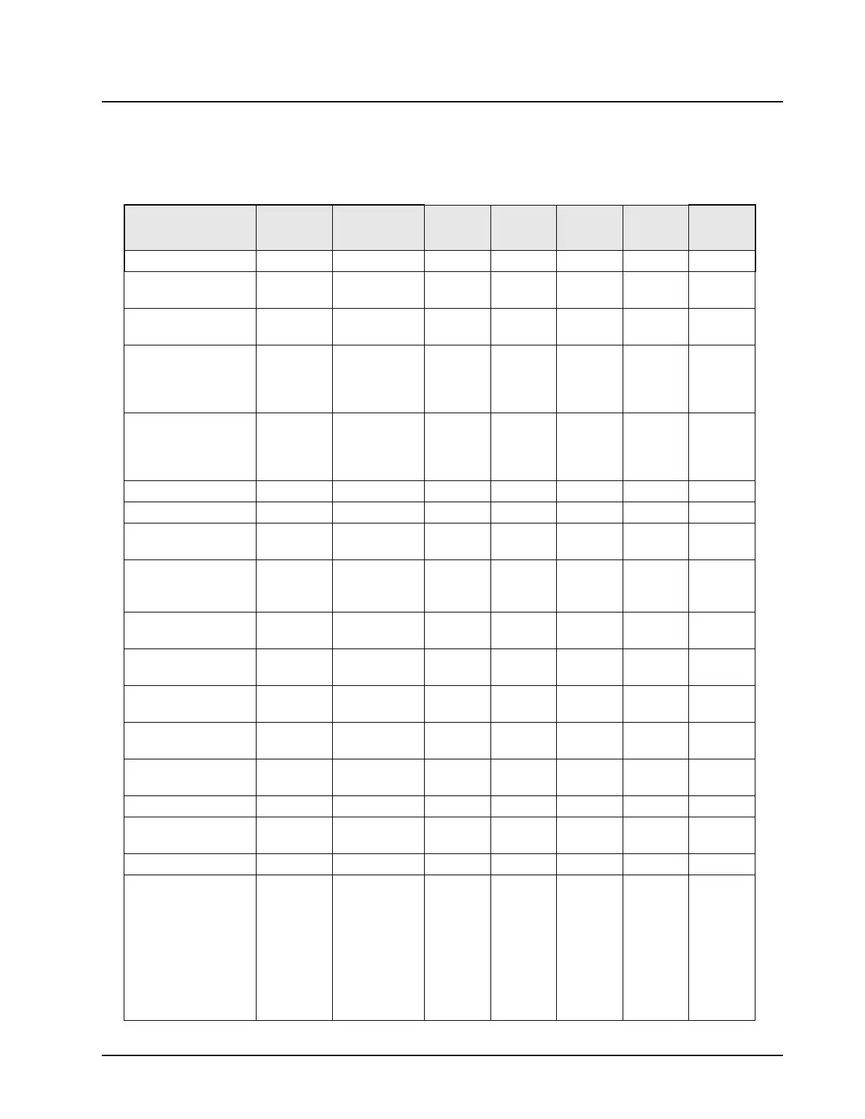
Please refer to “Chapter 7. Schematics, Component Location Diagrams, and Parts Lists”, for detailed
circuitry and power distribution information and the various voltages used by the ICs on the main
board are shown in Table 3-1.
Table 3-1. Integrated Circuits Voltages
Integrated Circuit A+
UNSW_VCC
(3.0V)
SW_5V 1.55 V 3.3 V 2.8 V 1.88 V
OMAP IC U1000 U1000 U1000 U1000
Unbuffered inverter
for 32 kHz clock
U1004
Schmidt trigger for 32
kHz clock
U1009
Buffer array for
isolation from
Unswitched supplies
to OMAP
U1002
SSI line analog
switches
U1001
U1003
U1005
U1007
8MB SDRAM U1300
2MB Flash U1301
TPS65012 PWR MGT
IC
U2100
Indicator LEDs NAND
Gates
U2101
U2102
U2103
USB Enable
MOSFET
Q2100
UNSW_VCC Linear
Voltage Regulator
U2201
SW_5V Switching
Voltage Regulator
U2200
ATTiny13
Microcontroller
U2302
Flip Flop to control
SW_B+
U2302
USB / UART MUX IC U3100
USB Current Limiter
IC
U3101
Volume Knob ADC IC U4201
All LEDs D4100
D4101
D4102
D4103
D4104
D4105
D4106
D4107
D4108

 Loading...


