June 15, 2005 6815854H01-A
4-32 Troubleshooting Procedures: Receiver Front-End (RXFE)
4.11 Receiver Front-End (RXFE)
This section provides band-specific troubleshooting procedures for the receiver front-end.
4.11.1 VHF (136–174 MHz) Band
Use this information, along with the theory of operation, to diagnose and isolate the cause of failures.
The principle tools needed to troubleshoot a circuit to the component level are the schematic and the
theory of operation.
In addition to the schematic and theory, you can use the troubleshooting flowcharts in "Chapter 5.
Troubleshooting Charts" that will guide you through a sequence of tests and checks designed to
isolate problems.
Prior to troubleshooting, it is important to review the theory of operation including specific
precautions and troubleshooting methods. Because much of the radio’s circuitry operates at a high
frequency, measurements must be taken carefully.
4.11.2 UHF Range 1 (380–470 MHz) Band
Use this information, along with the theory of operation, to diagnose and isolate the cause of failures.
The principle tools needed to troubleshoot a circuit to the component level are the schematic and the
theory of operation.
In addition to the schematic and theory, you can use the troubleshooting flowcharts in "Chapter 5.
Troubleshooting Charts" that will guide you through a sequence of tests and checks designed to
isolate problems.
Prior to troubleshooting, it is important to review the theory of operation including specific
precautions and troubleshooting methods. Because much of the radio’s circuitry operates at
400 MHz, measurements must be taken carefully.
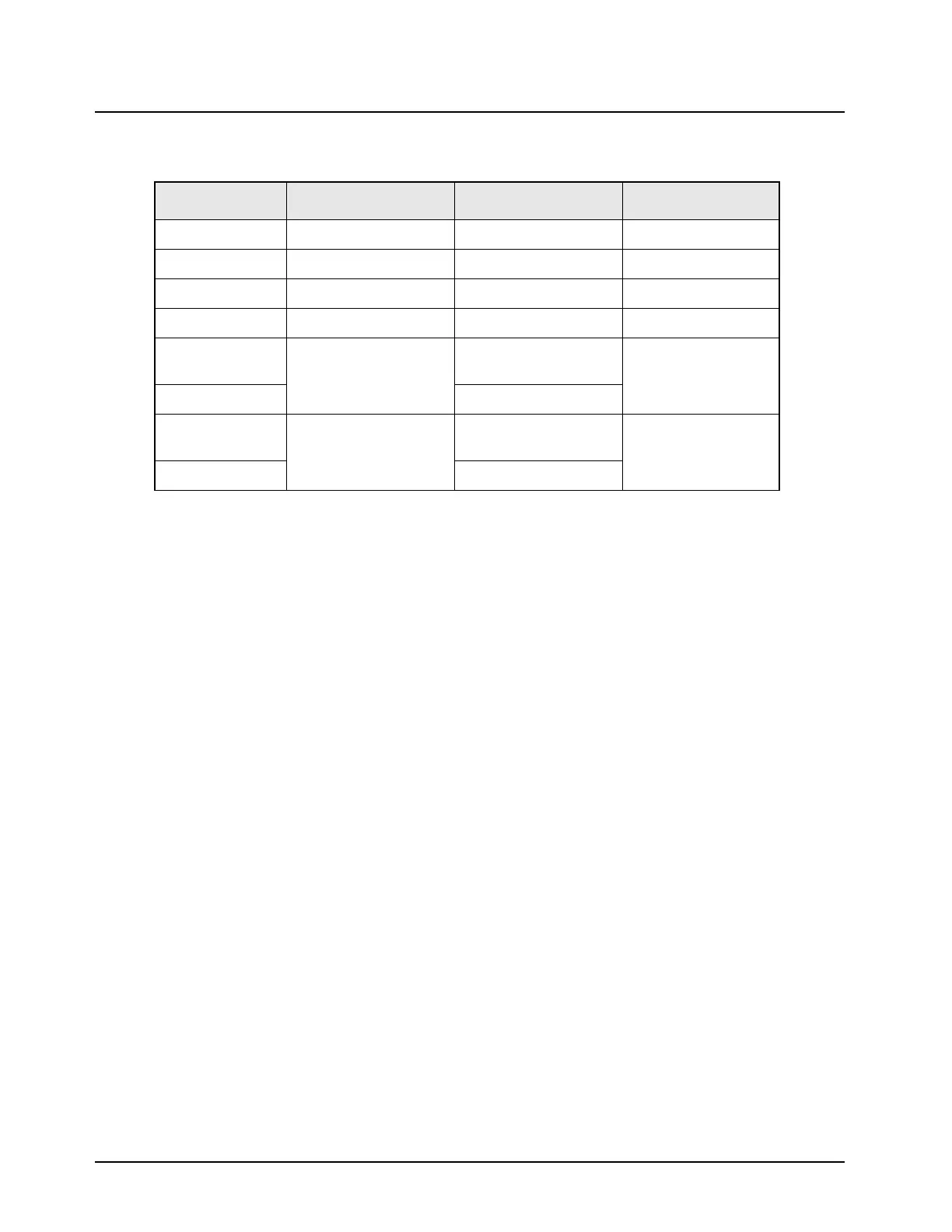
Table 4-19. Standard Operating Bias: VIP Lines (Dash Configuration)
Nominal Value Signal Name Range/State Probe Locations
NA VIP_OUT_1_5v Not accessible J0401-13
NA VIP_OUT_2_5v Not accessible J0401-14
NA VIP_IN_1_5v Not accessible J0401-15
NA VIP_IN_2_5v Not accessible J0401-16
SW_B+ level VIP_OUT_1_12v Deactivate = relay
closed
J0401-11, J2-18
0.3 V to 0.5 V Activate = relay open
SW_B+ level VIP_OUT_2_12v Deactivate = relay
closed
J0401-12, J2-19
0.3 V to 0.5 V Activate = relay open
Note: The voltage levels on the microprocessor side are at 2.85 V levels. The microprocessor is
not designed to drive the relay, but instead, is intended to drive the transistors inside the control
head or on the interconnect board. Be careful when changing jumpers.
Note: The impedance of the relay is why the SW_B+ does not damage the VIP line. Never connect
SW_B+ directly to a VIP line.

 Loading...


