EasyManua.ls Logo

NEC iPasolink 200 User Manual

NEC iPasolink 200
166 pages
To Next Page IconTo Next Page
To Previous Page IconTo Previous Page
Page #22 background image
4-8 IDU MOUNTING
NWD-107460-02E Installation
4.3 Fuse Replacement
When the power is supplied to the power supply connector but the IDU can not be
powered, check the conduction of fuse in the IDU.
1. Disconnect power supply cable from power supply connector.
Fig. 4-1 IDU Front View
2. Disconnect cables connected to the IDU in the following order.
2-1. Disconnect IF cable from IF IN/OUT connector.
The adapter is reused.
2-2. Disconnect ground cable from the ground terminal.
3. Loosen fuse cap on the IDU.
4. Remove the fuse from the fuse holder.
5. Check conduction of the broken fuse using tester.
6. Check conduction of the reserved fuse using tester.
7. Replace the broken fuse with reserved one.
8. Set the replaced fuse to the fuse holder.
9. Fasten the cap of the fuse on the IDU.
10. Connect power supply cable to power supply connector.
11. Check that the power is on.
This step is the end of the procedure.
Power supply
connector
Fuse cap
Submission Prohibited
NEC Internal Use Only

Table of Contents

Question and Answer IconNeed help?

Do you have a question about the NEC iPasolink 200 and is the answer not in the manual?

NEC iPasolink 200 Specifications

General IconGeneral
BrandNEC
ModeliPasolink 200
CategoryNetwork Hardware
LanguageEnglish

Summary

Installation Overview

Product Packages and Contents

Unpacking Procedures for IDU and ODU

IDU (Indoor Unit) Mounting

SFP Module Installation

Details on installing Small Form-factor Pluggable (SFP) transceiver modules for Gigabit Ethernet or SDH.

FAN Unit Replacement

Procedure for replacing the cooling fan unit within the IDU, including recommended replacement intervals.

Fuse Replacement

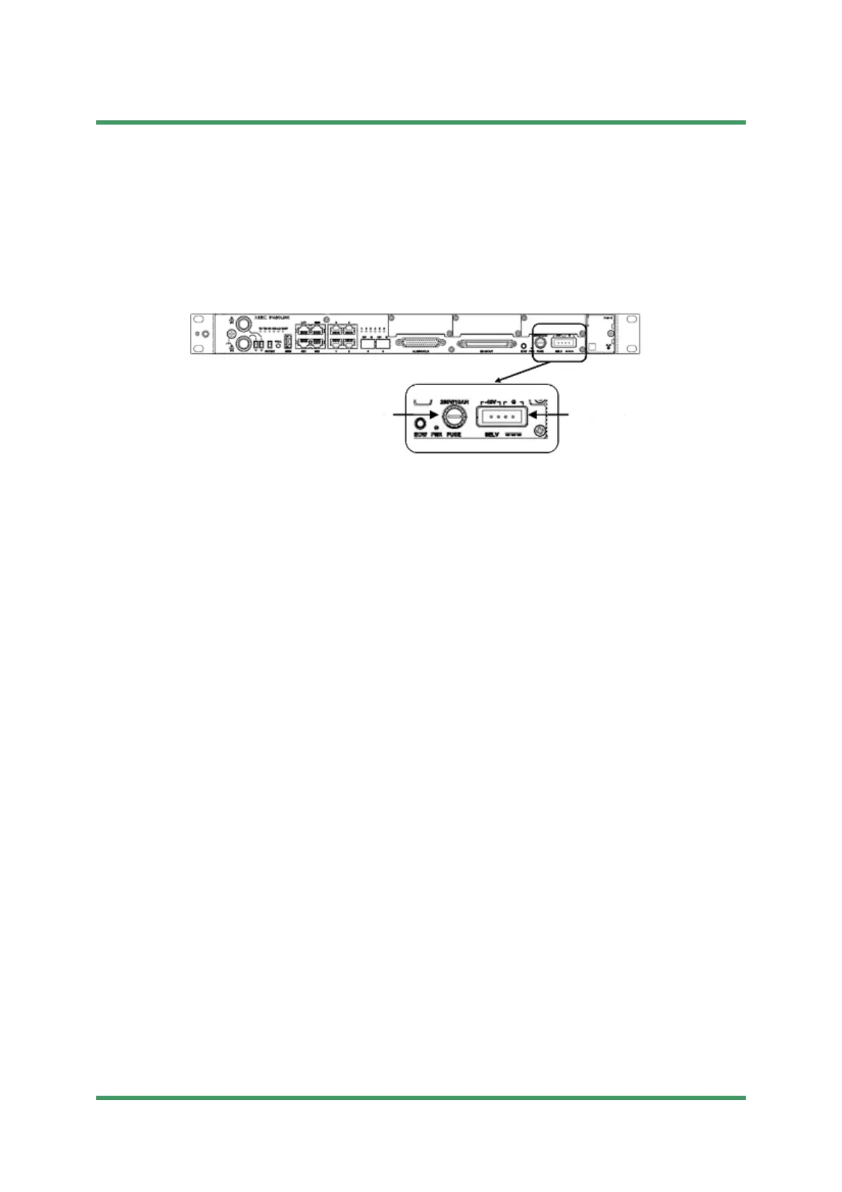
Steps for replacing a blown fuse in the IDU, including troubleshooting power issues.

ODU (Outdoor Unit) Mounting

Antenna Direct Mounting

Covers direct mounting of ODU to antennas, including different bracket types and connection methods.

Feeder Connection

Details on connecting coaxial and waveguide cables for ODU installation.

Other Mounting Options

Describes wall mounting and rack mounting procedures for the ODU.

Hybrid Combiner Installation

Instructions for installing hybrid combiners with dual-polarized antennas for 1+1 or 2(1+1) systems.

Cable Termination Procedures

5D Coaxial Cable Termination

Step-by-step guide for terminating 5D coaxial cables with TNC-P and N-P connectors.

8D Coaxial Cable Termination

Instructions for terminating 8D coaxial cables, specifically TNC-P connectors for IDU IF IN/OUT.

Other Cable Types and Termination

Covers power supply cables, balanced signal, and auxiliary signal cable termination.

Wiring and Cable Forming

Frame Grounding Procedures

Waterproof Protection of Connectors

Antenna Orientation and Alignment

Antenna Direct Mounting Type Alignment

Covers azimuth and elevation adjustments for ANDREW VHLP and RFS SB1/C-Mount brackets.

Waveguide Connection Type Alignment

Procedure for adjusting azimuth and elevation for waveguide-connected antennas.

Related product manuals