CABLE TERMINATION 6-1
Installation NWD-107460-02E
6. CABLE TERMINATION
In this section, list of tools, materials and the method for cable termination are
described. The list of applicable cable is shown in Table 6-1.
Notes
1 In 1+1 system, the difference between the No.1 channel IF cable length
and the No.2 channel IF cable length should be within 100 m.
(differential absolute delay time: within 500 ns)
2 When the N (Male) straight connector is attached to the IF cable, use of
the TNC (Male) - N (Female) (NJ-TNCP-LA) L-angle adapter is needed
to connect to the IDU.
3 Use shielded cables which are connected to the D-Sub/RJ-45 connector
to suppress interference from affecting the signal and to reduce
electromagnetic radiation which may interfere with other signal cables.
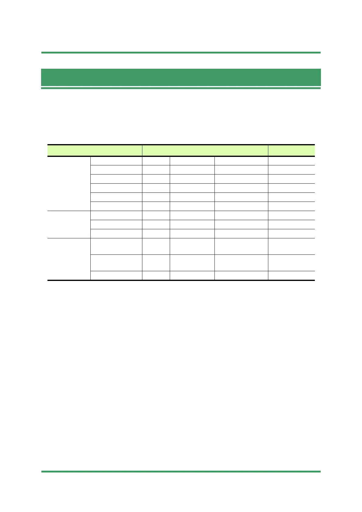
Table 6-1 List of Applicable Cable
Applicable Cable Connector Type Model# Procedure#
5D Coaxial
Cable
for IDU TNC-P L-angle TNC150(R0) Procedure 6-1
for IDU TNC-P L-angle 300PTR-C-NC Procedure 6-2
for IDU TNC-P L-angle TNC156(R0) Procedure 6-3
for ODU N-P L-angle 300PNR-C-NC Procedure 6-4
for ODU N-P Straight 300PNM-C-NC Procedure 6-5
for ODU N-P Straight N435(R0) Procedure 6-6
8D Coaxial
Cable
for IDU TNC-P L-angle TNC141(R0) Procedure 6-7
for ODU N-P L-angle N-LP-8DFB(B) Procedure 6-8
for ODU N-P Straight N416(R0) Procedure 6-9
Other Cables for power supply AMP Housing &
socket contacts
AMP: 1-178288-4 or
DK-3100S-04R
Procedure 6-10
for 120 ohms
balanced signal
D-sub Crimping --- Procedure 6-11
for auxiliary signal D-sub High Density --- Procedure 6-12
Submission Prohibited
NEC Internal Use Only
 Loading...