Multiple devices, even of different types, can be connected to the STOP
SAFETYEDGEinputifappropriatelyorganised:
-NOdevices:connectthe8.2kΩresistorinparalleltothedevice;
-NCdevices:connectthe8.2kΩresistorinseriestothedevice;
- You can connect multiple NC devices “in series” with each other without
quantity limits;
-Iftherearemultipledevices,allmustbeconnected“incascade”withasingle
8.2kΩterminalresistance;
- You can also create a combination of NO and NC types, by placing the two
contacts“inparallel”.Inthiscase,youneedtoplacea8.2kΩresistance“in
series”withtheNCcontact;thisalsomakesitpossibletoputthreedevices
together:NO,NCand8.2KΩ.
3.7 - Connecting a radio receiver
The control unit has an SM connector for connecting an SMXI, SMXIS, OXI,
OXIT or similar radio receiver (optional accessory, not supplied).
To connect the radio receiver, you must disconnect the mains power supply
from the control unit and insert the receiver as shown in Fig. 8.
Table2showstheactionsperformedbythecontrolunitaccordingtotheacti-
vated outputs or the commands sent by the radio receiver.
Note - For further information, refer to the instruction manual for the receiver.
TABLE 2
SMXI, SMXIS Receiver in “Mode 1 or 2”
output description
Output No. 1 Step-by-Step
OutputNo.2
Partial open; factory setting: it opens to halfway (this
may be changed during the position acquisition phase
or by using the Oview programmer)
OutputNo.3 Open
OutputNo.4 Close
OXI, OXIT receiver programmed in “extended Mode 2”
command description
Command No. 1
Step-by-Step
CommandNo.2
Partial open; factory setting: it opens to halfway (this
may be changed during the position acquisition phase
or by using the Oview programmer)
CommandNo.3
Open
CommandNo.4
Close
Command No. 5
Stop
CommandNo.6
Step-by-Step Condominium
Command No. 7
Step-by-Step High priority
CommandNo.8
Partialopen2
CommandNo.9
Partialopen3
Command No. 10
Open and Lock automation
Command No. 11
Close and Lock automation
CommandNo.12
Lock automation
CommandNo.13
Release automation
CommandNo.14
Timed Courtesy light
Command No. 15
CourtesylightON/OFF
3.8 - Initial startup and electrical connections test
Aftersupplyingpowertothecontrolunit,carryoutthefollowingchecks:
•VerifythatthegreenL2LED(closetotheDIPswitches)ashesregularly,with
afrequencyof1ashpersecond.
•Ifthesystemisequippedwithphotocells,checkthattheirLEDsashcor-
rectly(RX);thetypeofashingisnotsignicantbecausethatdependsonother
factors.
•EnsurethattheredSAFETYLEDnearthekeyboardcableconnectorisper-
manentlyON(seeSafetyLEDDiagnosticstable,Paragraph6.2).
If any one of these tests fails to comply with requirements, you must discon-
nect the electrical power from the control unit and check the various electrical
connections made previously.
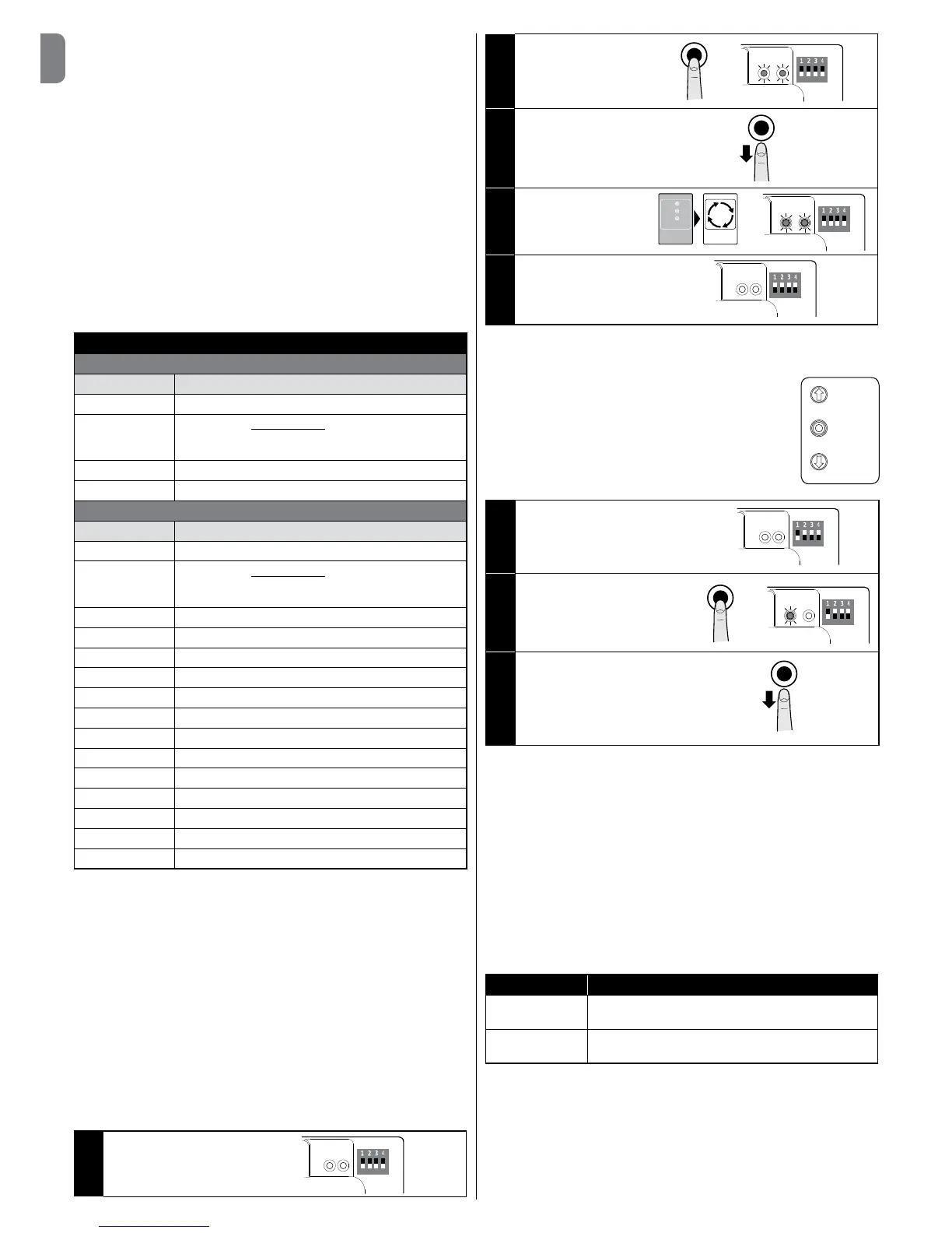
3.9 - Total deletion of the control unit memory
You can delete all the data stored on the control unit and restore it to its original
state with the default settings.
01. Setdipswitches1-2-3-
4toON=theredand
green ledsstartashing
quickly
ON
OFF
02. Press and hold the
STOPbuttonfor3sec.
until the green and red
leds remain lit
3”
ON
OFF
03. Release the STOP
button
04. At this point the control
unit performs a RESET
=theredandgreenleds
startashingquickly
ON
OFF
RESET
05. Setdipswitches1-2-3-
4toOFF
ON
OFF
3.10 - Recognition of the safety devices and the Opening and
Closing positions
Afterperformingtheinitialstartup(paragraph3.8)andbe-
fore setting the gate Opening and Closing positions, you
must have the control unit run the recognition phase of
theconnectedsafetydevicesonthe“STOPSafetyEdge”
input.
CAUTION! - During the recognition phase, at least
one safety device must be connected to the control
unit.
OPEN
STOP
CLOSE
01. Setdipswitch1toON=
-GreenLEDbeginstoash
rapidly
-RedLEDisOFF
ON
OFF
02. Press and hold the STOP button
until the red led comes on and
remainslit(afterabout3sec.)
3”
ON
OFF
03. Release the STOP button
This procedure must be repeated if a modication is made to the
devices connected to the “STOP Safety Edge” terminal (for example,
after connecting a new device to the control unit).
After performing the recognition of the safety devices on the automated sys-
tem, the control unit must recognise the gate Opening and Closing positions.
CAUTION! - The recognition procedure of the safety devices and the
gate Opening and Closing positions must be done consecutively,
without interruption. You can not perform the recognition of the safety
devices at one time and the recognition of the positions at another
time.
3.10.1 - Recognition of the Opening and Closing positions with
mechanical limit switch
Youcanprogram2positions,asfollows:
Position Meaning
Opening Maximumopeningposition.Whenthegatereaches
this position it stops.
Closing Maximumclosingposition.Whenthegatereachesthis
position it stops.
Caution! - If the direction of rotation does not correspond to the direc-
tion set (Open button = opening direction), you need to invert the “V”
and “W” connections (phase inversion) in the motor connector (g. 9).
 Loading...