Toperformtheprocedure,proceedasfollows:
01.
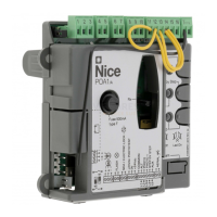
MoveDIPswitch1toOFF
ON
OFF
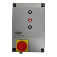
02.
Pressthe“Open”buttontomove
thegatetoitsmaximumopenpo-
sition
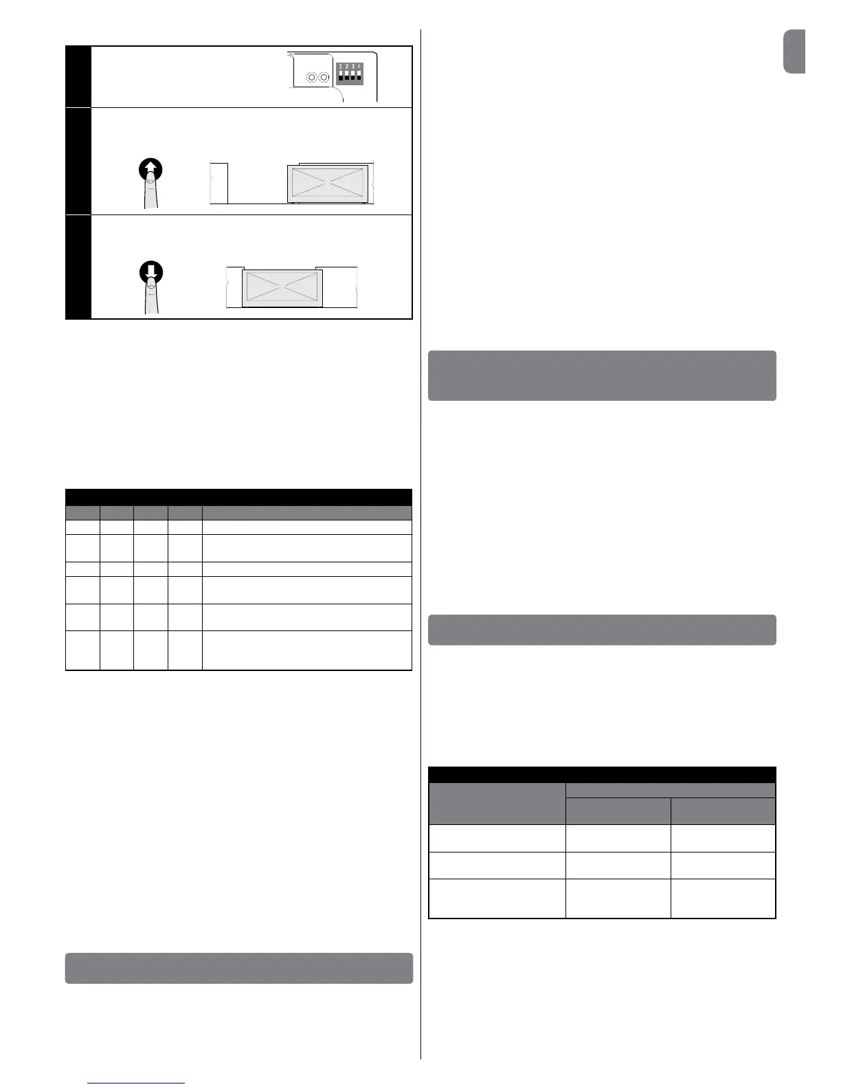
03. Pressthe“Close”buttontomove
the gate to its maximum closed
position
CAUTION! – The recognition phases must not be interrupted. If there
is an interruption, you must repeat the entire recognition process. If at
the end of the recognition phase, the red LED ashes 9 times-pause-9
times, it means that an error has occurred.
If instead it ashes 3 times-pause-3 times, reset the error by pressing
the STOP button and invert the opening limit switch connection with
that of the closing limit switch at the LIMIT SWITCH terminal (Fig. 5).
The position recognition phase can be repeated at any time, also after
the installation.
3.11 - Operating modes
CAUTION! - If the functions of Table 3 are programmed with the Oview
programming unit, it is necessary to set the dip switches to OFF.
TABLE 3
DIP1 DIP2 DIP3 DIP4 Function
OFF OFF OFF OFF Hold-to-run movement
ON x OFF OFF Acquisition of positions and status of the ALT
input
OFF ON OFF OFF Rotation direction of the encoder reversed
OFF x OFF ON Industrial mode (semi-automatic opening –
hold-to-run closing), if positions recognised
OFF x ON OFF Semi-automatic mode, if positions recog-
nised
OFF x ON ON Automatic mode with adjustable pause time,
ifpositionsrecognised(seepara.6.1.2“Other
functions”forinfoonsavingthepausetime)
3.12 - Oview programming unit
Using the Oview programming unit allows you to manage the installation,
maintenance and diagnosis of the entire automated system in a thorough and
rapid manner.
YoucanconnectOviewtothecontrolunitviatheIBT4Ninterfaceusingabus
cablewith4wiresinside.
ToaccesstheBusT4connector,youneedtoopenthecontrolunitbox,plug
the IBT4N connector into theappropriateslot and then connect the Oview
programmer (Fig. 10).
Oview can be used at a maximum cable distance of 100 metres from the
control unit; it can be connected simultaneously to multiple control units (up to
16)andcanremainconnectedevenduringnormaloperationoftheautomated
system. When working with Oview, it is very important to observe the instruc-
tions in the Oview instruction manual.
If there is an OXI radio receiver in the control unit, when you use Oview you can
have access to the parameters of the transmitters memorised in the receiver.
Forfurtherinformation,refertotheOviewinstructionmanualorthecontrolunit
function sheet available from the website www.niceforyou.com
CAUTION! - If the functions of Table 3 are programmed with the Oview
programming unit, it is necessary to set the dip switches to OFF.
4
TESTING AND COMMISSIONING
The testing and commissioning phases are the most important when creating
anautomatedsysteminordertoensuremaximumsafety.Thetestingproce-
dure can also be performed as a periodic check of the automation devices.
Thesephasesmustbeperformedbyqualiedandexperiencedpersonnelwho
must take charge of establishing the tests necessary to verify the solutions adopt-
ed in respect of risks and verify the compliance of the system with applicable
standards, legislation and regulations, in particular all requirements of the standard
EN12445whichestablishesthetestmethodsforcheckingautomatedsystems
fordoorsandgates.Theadditionaldevicesmustundergospecictesting,both
in terms of their functions and in terms of their interaction with the control unit;
therefore, you need to refer to the instruction manuals for the individual devices.
4.1 - Testing
The sequence of steps to be performed when running the testing phase, as
describedbelow,referstoatypicalsystem:
1Check that all the instructions in the “Installation warnings” chapter have
been rigorously complied with.
2 Release the motor. Check that the gate can be manually manoeuvred with a
forcenogreaterthan225N.
3 Lock the motor.
4 Using the control devices (transmitter, push button, key switch, etc.), test the
Opening, Closing and Stopping of the gate, ensuring that the movement of
thegateleavescorrespondstospecications.Testseveraltimestoassess
the movement of the gate and check for any defects in assembly or adjust-
ment and for any particular points of friction.
5 Check, one by one, that all the safety devices featured in the system (photo-
cells, sensitive edges, etc.) work properly.
6 If the dangerous situations caused by the movement of the gate leaves have
been safeguarded against by limiting the impact force, the impact force must
bemeasuredaccordingtotheEN12445standard.
5
INSTALLATION AND ELECTRICAL CONNECTION
OF TWO CONTROL UNITS FOR LEAVES MOVING
IN OPPOSITE DIRECTIONS
To create an automation consisting of two leaves moving in opposite directions,
it is necessary to use two control units connected as shown in Fig. 11.
The motors and limit switches must be connected to each control unit. The
warning light and the G.O.I. (Gate Open Indicator) can be connected to any
one of the two control units, or can be installed one on each control unit.
mustbeplacedparalleltooneanother;the“Common”inputcanbeconnected
to either one of the two control units.
Connectinparallelsafetyedge(8k2/OSE)“–”connectorsofbothcontrolunits.
Congurethe“Open”inputas“Condominium”usingtheO-Viewprogrammer,
which allows for synchronising the leaves should the two control units lose their
synchronisation.
Withthiscongurationitisimportanttorememberthat:
• the intervention of the sensitive edge only impacts the single leaf;
• the red STOP key only impacts the single leaf;
• the intervention of the thermal protection device only impacts the single leaf.
6
FURTHER DETAILS AND DIAGNOSTICS
6.1 - Further details
6.1.1 - Signals when switching ON
When the DPRO500 control unit is switched ON, the reaction of the green OK
L2ledandtheredWARNINGL1LED isimportant,asshowninTable4. In
particular,itindicateswhether:
- The recognition of the Opening and Closing positions is correct;
- The recognition of the (sensitive edge) safety device is correct and what kind
of safety device has been recognised.
TABLE 4
Signals when
switched on
Signal
GREEN OK
L2 LED
RED WARNING
L1 LED
Blank memory (no acquired
position or safety device)
Rapidashingfor5
seconds
Rapidashingfor5
seconds
Positions acquired correctly
and“8k2”safetyrecognised
Rapidashingfor2
seconds
Justoneslowash
Positions acquired correctly
and“OSE”safetydevice
recognised
Rapidashingfor2
seconds
Twoslowashes
AfterprovidingthesignalsshowninTable4,theDPRO500controlunitshows
anyerrorsthroughDiagnosticsusingtheOKL2ledandtheWARNINGL1LED.
6.1.2 - Other functions
Status and diagnostics indicator (terminal on the keyboard)
Thecontrolunitallowsyouto connecta24V-5Wmax. indicatorlightto the
“indicator”terminalonthepushbuttonpanelhousedinsidetheboxcover(Fig.
12:terminal1-,2+).The“indicator”canbeinstalledonthecoveritself,by
making a hole on the latter, or it can be installed outside the control unit at a
maximumdistanceof2mfromthelatter.
CAUTION! - The output is not protected against short-circuits.
 Loading...