This“indicator”functionsinthefollowingway:
- off when the safety chain is open (ALT inp, red STOP button, thermal protec-
tion or release)
- ashes0.5sON,0.5sOFFwhenitworksproperly
- shows the same diagnostics as the red L1 WARNING LED when there are
“seriouserrors”(Paragraph6.2).
Setting the pause time for automatic closing
1 SetDIPswitches3and4toON.
2 Send a command to open the gate so as to move the gate to its fully open
position.
3 Once this position is reached, wait for a period of time equal to the required
pause time for automatic closing and then command the gate to close. The
pause time for automatic closing is now saved.
Inordertochangethepausetime,setdip3and4toOFFandthenbacktoON.
At this point you must repeat the sequence of opening, pause time and closing.
CAUTION! - WhenDIPswitch4ismovedtotheOFFposition,thepausetime
is deleted.
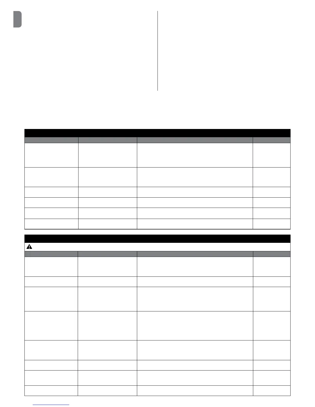
6.2 - Diagnostics
Some devices are equipped to display messages to identify their status and faults. The following table describes the various alarm signals according to the type
ofproblem.ThesealarmsignalsareprovidedbyappropriateashesofthegreenOKL2LEDandtheredWARNINGL1LEDandfromtheashinglight(ifthere
is one) connected to the specially programmed control unit outputs.
DIAGNOSTICS GREEN OK L2 LED
Signal Cause Solution Flashing light
2ashes-shortpause
2ashes-longpause
Triggering of a photocell
At the start of the manoeuvre, one or more photocells fail to give the
enable signal; check for obstacles and whether the photocells are in-
terfering with each other’s IR. When the safety devices have intervened,
the automation can be controlled with a person present through the
wired controls. It is not possible to send commands via radio.
Flash
4ashes-shortpause
4ashes-longpause
Triggering of the STOP input
At the start of or during the manoeuvre, the STOP or ALT input was
triggered; identify the cause. When the safety devices have intervened,
the automation can be controlled with a person present through the
wired controls. It is not possible to send commands via radio.
Flash
6ashes-shortpause
6ashes-longpause
Manoeuvre limiting device --- Flash
9ashes-shortpause
9ashes-longpause
Automation system locked Sendthe“ReleaseAutomation”commandorcommandthe
manoeuvrewith“Step-by-StepHighPriority”.
Flash
TheLEDscomeonfor3
seconds
Lock automation --- Flash
2ashesof1secondwith
pause of 1.5 seconds
Automation system released --- Flash
DIAGNOSTICS RED WARNING L1 LED
Certain signals can be cancelled by pressing the red STOP button
Signal Cause Solution Flashing light
5ashes-shortpause
5ashes-longpause
EEPROM error - Error in the
internal parameters of the control
unit
Disconnect and reconnect the power supply. If the error persists, run
the“Totaldeletionofthecontrolunitmemory”(paragraph3.8)and
rerun installation. If the condition persists, there may be a serious
fault and you will need to replace the electronic circuit board.
Flash
2ashes-shortpause
2ashes-longpause
Safety Test Error Rerun the recognition procedure for the safety devices connected to
thecontrolunit(paragraph3.9).
---
3ashes-shortpause
3ashes-longpause
Error in direction of rotation
of the Encoder Or inverted limit
switch
Reverse the direction of rotation of the encoder by moving DIP switch
2toON(seeparagraph3.10).Ifthemotormountsamechanicallimit
switch, reset the error by pressing the STOP button and invert the
opening limit switch connection with that of the closing limit switch
at the LIMIT SWITCH terminal (Fig. A - page 4).
4ashes-shortpause
4ashes-longpause
Error with safety limit switches The gate has gone past the safety limit switches during Opening
or Closing. Move the gate manually to about half way up using the
emergency manoeuvre system (see the manual of the motor) and
press the STOP button on the cover in order to restore operation.
Assess whether you need to change the previously acquired Open-
ing/Closingpositions.
---
6ashes-shortpause
6ashes-longpause
Error with contactor Disconnect all the power lines for a few seconds, then try sending a
command again; if the problem persists, there may be a serious fault
on the circuit board or on the connections of the motor. Carry out
checks and replace parts, if required.
---
7ashes-shortpause
7ashes-longpause
RS485communicationerroron
Encoder
Check that the motor-control unit cable is connected correctly, in
particulartheencodercable(6colouredwires).
---
8ashes-shortpause
8ashes-longpause
Encoder error Check that the motor-control unit cable is connected correctly, in
particulartheencodercable(6colouredwires).Reruntherecogni-
tion procedure of the Opening and Closing positions.
---
9ashes-shortpause
9ashes-longpause
Error in limit switch acquisition Repeat the recognition procedure of the Opening and Closing posi-
tions.
---
 Loading...