3
ELECTRICAL CONNECTIONS
CAUTION!
– Before you proceed to make any electrical connections make sure
that the power supply is disconnected;
– Connections must only be carried out by qualied personnel.
– You must put a device on the electricity supply line that ensures complete
disconnection of the automated mechanism from the mains supply. The
disconnection device must have contacts with an opening distance large
enough to permit complete disconnection under the conditions sanctioned
by overvoltage category III, in accordance with installation regulations. The
device ensures quick, safe disconnection from the power supply if needed,
and must therefore be in a position that is visible from the automation mech-
anism. If, on the other hand, it is located in a position which is not visible,
there must be a system for preventing accidental or unauthorised reconnec-
tion to the mains supply to prevent this risk. The disconnection device is not
supplied with the product.
– Selecting the power supply voltage:
The control unit can function correctly with three-phase or single-phase
power(seewiringdiagrams),witheither400Vor230Vvoltage.
Thedefaultsettingisthree-phase400Vpowersupplyvoltage.
To select the 230 V single-phase power supply, observe the instructions
speciedinChapter3.2
3.1 - Connecting the three-phase power supply cable
To make the electrical connection refer to Fig. 3.
A16ACEEplugmustbeconnectedtoterminalsL1,L2andL3andtothe
PE terminal.
3.2 - Connecting the single-phase power supply cable
To make the electrical connection refer to Fig. 4.
A Schuko plug must be connected to terminals L1 and L3 and to the PE
terminal.
3.3 - Changing the power supply through the jumper
The power supply to the control unit can be changed through the jumper, as
explainedbelow(Fig. 5)
01. Remove the top cover
02. Extractthejumper(defaultposition3x400V)usingneedle-nosepliers
03. Insertthejumper(1x230V)
04. Re-insert the top cover
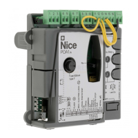
3.4 - Description of the electrical connections (Fig. A): power
supply, safety and control devices and accessories
You can connect control devices with “Normally Open” (NO) or “Normally
Closed”(NC)contactstothe8,9,10and11inputs.Youcanthenmakeuseof
oneoftheseinputsoracombinationthereof,aswellastheSTOP/ALTinputsif
appropriate,toconnectanexternalpushbuttonpanel,forexample,oraswitch
with a rope connected to the ceiling.
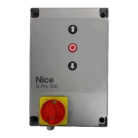
PUSH BUTTONS - Input for connecting the push button panel on the cover
ofthebox.
ENCODER - Input for connecting the wiring of the electronic limit switch
(Nice encoder). Not usable in this version.
COMMON (8)-24VDCinputthatactsasacommoninputfortheOPEN,
CLOSE and ING1 inputs and positive for power supply to the services.
OPEN (9) - Input for devices which control only the opening movement. It is
possibletoconnectcontactsofthe“NormallyOpen”typetothisinput.
CLOSE (10) - Input for devices which control only the closing movement.
Itispossibletoconnectcontactsofthe“NormallyOpen”typetothisinput.
ING1-photo- (11) - Normally Closed (NC) input for devices that control the
movement of the automation. If this input is properly programmed with the
NiceOviewprogrammer,youcangetthefollowingoperatingmodes:
– Step-by-step
– Partial Open
– Open
– Close
– Photo (default)
– Photo 1
– Alt in opening
– Alt in closing
Foradescriptionandinstructionsonhowtoprogramtheavailablefunctions,
refer to the Oview function sheets for DPRO500.
ALT - Input for devices that stop a manoeuvre when in progress; connect
contactsofthe“NormallyClosed”type.
SAFE - Input for connecting the thermal protection device of the motor.
CAUTION! - It is only used for motors with mechanical limit switches. Leave
“unconnected”withmotorswhichhaveelectroniclimitswitches.
LIMIT SWITCH - Input for connecting mechanical limit switches.
(1) limit switch common
(2)limitswitchopen
(3)pre-limitswitchclose
(4)limitswitchclose
STOP-Inputforconnectingresistivesensitiveedges(8k2)oropticalsensi-
tive edges (OSE), as described below (Fig. 6):
OSEConnection:
- 5 Òpositive12VDC(+)(brownwires)
-6Ò signal (S) (green wires)
- 7 Ò GND negative (-) (white wires)
8k2Connection:
-Connectthe8.2kΩresistorbetweenterminals6(signal-S)and7(nega-
tive - GND)
IBT4N-InputforconnectingtheOviewprogrammer,withtheIBT4Nadapt-
er.CAUTION-disconnectthepowersupplybeforeconnecting/disconnect-
ing the programmer.
ANTENNA
- Input forconnecting the radioreceiver aerial(Note: the
aerialisbuiltintotheNiceLUCYB,MBLandMLBTashinglights).
OUT (CONNECTOR FOR NDA040)-Connector for NDA040accessory
card that adds two outputs to voltage-free contacts. These outputs can be
properlyprogrammedwiththeNice Oviewprogrammer.Fora description
andinstructionsonprogrammingtheavailablefunctions,seetheNDA040
accessory board manual.
MOTOR - Output for connecting the single-phase and three-phase motor.
Forsingle-phasemotors:
U - common
V - opens
W - closes
LINE - Input for connecting the power supply.
L1-L2-L3:THREE-PHASEconnection
L1-L3:SINGLE-PHASEconnection
PE - Input for the earth connection for the control unit and motors.
IMPORTANT!
We DO NOT recommend that you connect
any device or accessory not mentioned in this
instruction manual.
The manufacturer declines all responsibility
whatsoever for any damage due to improper
use of the various system devices that does not
comply with the instructions in this manual.
For more information, please contact the Nice
Customer Service.
3.5 - Electrical connections of the control unit
CAUTION! – Before you proceed to make any electrical connections
make sure that the mains power supply is disconnected.
Afterattachingthecontrolunitboxandpreparingtheholesforroutingtheelec-
tricalcables(seeparagraph2.3),maketheelectricalconnectionsasfollows:
01. Firstconnectthepowersupplycable:
- for the three-phaselineseeParagraph3.1andFig. 3
- for the single-phaselineseeParagraph3.2andFig. 4
02. Then,connectthepowersupplycablefromthemotor:
- Motor with mechanical limit switch (Fig. 7)
03. Lastly, connect the electrical cables of the various available accessories,
referring to Fig. Aandparagraph3.3.
Note – To facilitate connecting the cables, you can remove the terminals
from their positions.
3.6 - STOP SAFETY EDGE Input
ThefunctionoftheSAFETYEDGEinputistocausetheimmediatestopofa
manoeuvre when in progress followed by a short reverse manoeuvre.
This input can be connected to devices such as optical sensitive edges (OSE)
orthosewith8.2kΩconstantresistanceoutput.
During the recognition phase, the control unit recognises the type of device
connected and causes a “STOP” whenever any variation in the recognised
status occurs.
 Loading...