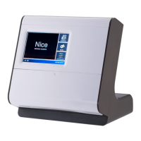
Mercury 310 Automated Gate System
Installation and Programming Manual
1919
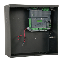
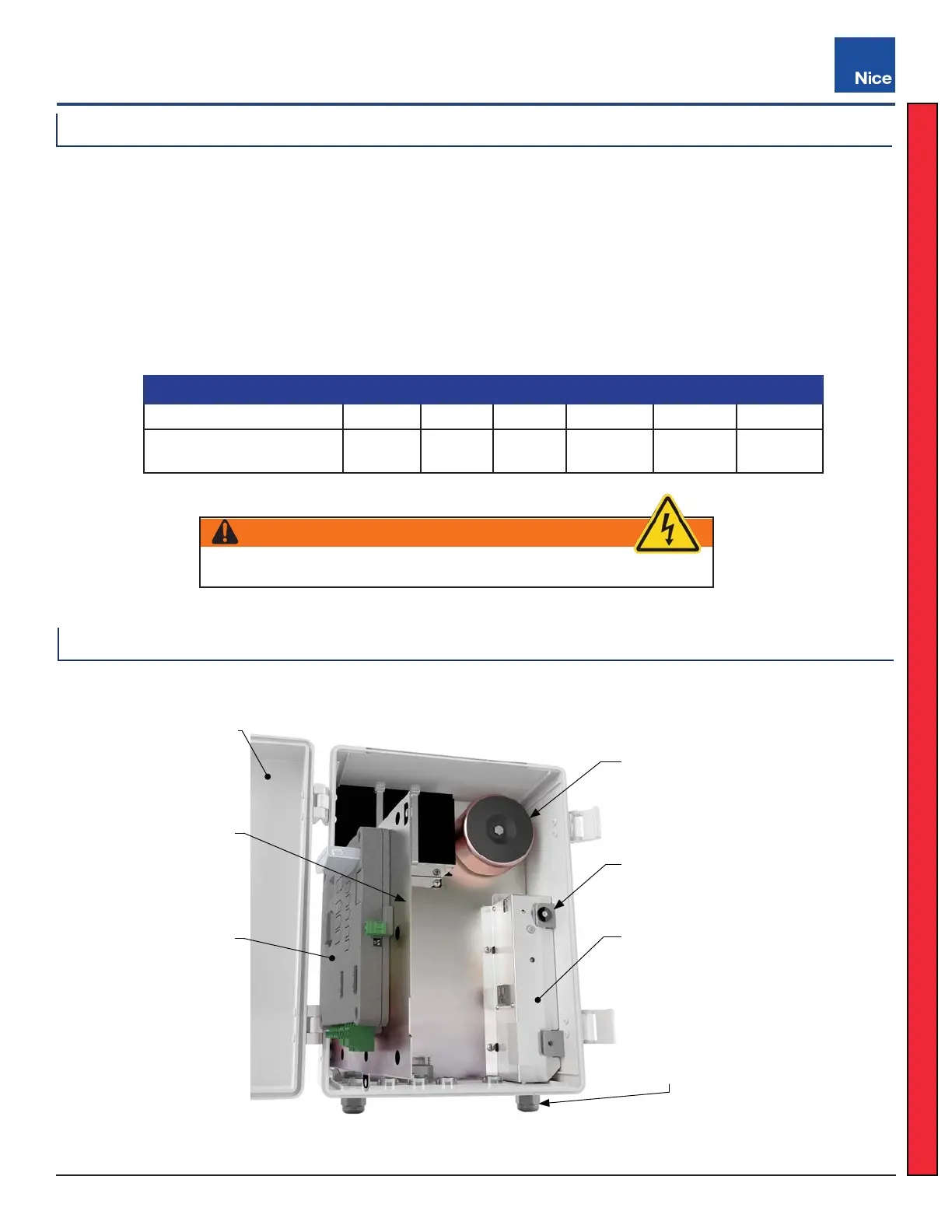
Power Supply Module Location
Maximum Run Per Wire Gauge
120V/AWG GAUGE 14 12 10 8 6 4
MAX RUN
180 FT
(54.8m)
280 FT
(85.3m)
460 FT
(140m)
700 FT
(213.3m)
1150 FT
(350.5m)
1800 FT
(548.6m)
Use the table below to determine high voltage wire size requirements.
’ Distance shown in the chart is measured from the operator to the power source.
’ If power wiring is greater than the maximum distance shown, a service feeder is recommended.
’ When large gauge wire is used, a separate junction box must be installed for the operator connection.
’ Wire table is based on stranded copper wire. Wire run calculations are based on a 120 VAC power
source with a 3% voltage drop on the power line, plus an additional 10% reduction in distance to allow
for other electrical losses in the system.
Access the power supply by opening the front cover, then pulling open the controller panel from the magnet.
WARNING
Mercury 310 controller accepts low voltage (<24VDC) power only.
Power Supply
Module
AC Power
Conduit
to Power
Supply
Controller
Panel Open
Mercury 310
Controller
Panel
Magnet
Transformer
Front Cover
Open
ACBOX310
5.1.2 Wire Run Sizing
5.1.3 Power Supply Wiring
www.ApolloGateOpeners.com | (800) 878-7829 | Sales@ApolloGateOpeners.com
 Loading...