Mercury 310 Automated Gate System
Installation and Programming Manual
5454
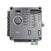
10.2 SAFETY SENSOR INPUTS
The Sensor Inputs, which are used to connect safety sensors, are listed below:
’ BlueBUS Input
’ 10K Ω Monitored Sensor Input (photo eyes, edge sensors, etc.)
CAUTION
The Mercury 310 controller Type A and Type C internal entrapment protection
meets the minimum UL 325 requirements, HOWEVER, a safe installation
free of hazards to persons and animals is required, so additional external
entrapment sensors may be needed to cover possible entrapment zones.
10.2.1 Auto Sensor Scan
When power is applied to the Mercury 310 controller, it performs a scan for connected external entrapment
sensors at the sensor inputs and “learns” the sensor by registering it in an internal sensor registry.
If the sensor input is tripped at power up, the sensor input LED will ash and power must be removed from the
controller and sensor wiring or alignment must be corrected before re-powering the controller and relearning
the sensors. The display will show what sensor is tripped and the associated LED will Flash.
10.2.2 Manual Sensor Scan / Clear
Once the controlller has a stored sensor at a specc input, the power-up scan will always expect to see that
sensor at the same input. The only way to remove that sensor, and clear the sensor registry, is to disconnect
the sensor and perform a manual scan as follows:
’ Press and hold the Stop/Clear button for ve (5) seconds. This will relearn the connected sensors.
NOTICE
Only a manual scan will uninstall learned sensors.
Mercury 310
WARNING
Disconnect the operator from power (both DC/Solar & Battery) when installing
any accessory or external entrapment sensor.
www.ApolloGateOpeners.com | (800) 878-7829 | Sales@ApolloGateOpeners.com
 Loading...