Mercury 310 Automated Gate System
Installation and Programming Manual
5858
10.4 10KΩSENSORINPUTS
OPEN = Open-Diection 10K Ω (N.O.)
CLOSE = Close-Direction 10K Ω (N.O.)
COM = Common (GND)
12V SW = 12VDC Output (Switched)
(STEP MODE)
REMOTE INPUT
N.O.
+V
+V
N.O.
N.O.
COM
10K Ω
SAFETY
SENSORS
+12 VDC
(OFF in Standby)
+12 VDC
GUARD
STATION
FIRE
DEPT.
Control
N.O.
Control
Control
LOOP 1
(Obstruct)
LOOP 2
(Shadow)
LOOP 3
(Exit)
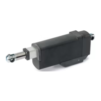
Motor 1
CONNECTIONS
ACTUATOR
Motor 2
SOLAR PANEL or
HIGH CURRENT
DC POWER
BATTERY
12 DC
+
+
_
_
+12 VDC
(OFF
in Standby)
ALARM
COM
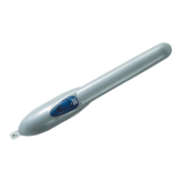
Example 10K Ω: EMX IRB
MON Photo Eye
Dual Direction 10K Jumper
A 10K sensor may be wired to provide simultaneous open-direction and close-direction sensing for a single
sensor by placing a jumper (i.e. wire) between the Open and Close 10K inputs. With the jumper in place, the
sensing lead may be installed to either input (Open or Close). This is the suggested way of wiring a wraparound
edge sensor on the leading end of a swing gate.
10.4.1 10K Ω Sensor Installation
1. Remove power sources from controller (battery and DC/Solar inputs).
2. Install photo eye pairs or edge sensors as appropriate (See page 11).
3. Wire sensors per manufacturer’s instructions. Wiring diagrams of
various compatible sensors can be found on the following pages.
4. Route sensor wires into control box and install into 10K input.
5. Reapply power to the controller.
6. At power-up, sensor inputs are scanned, and If 10K device is detected,
sensors are registered and associated input red LED lights.
7. Test the function of each sensor according to manufacturers instructions.
NOTICE
The Mercury 310 controller requires sensors with 10K terminated
outputs to meet the monitoring requirements of UL325.
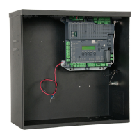
Mercury 310 Controller
Jumper
Common
Power
Sensor
Dual Direction 10K Sensor Wiring
Mercury 310
www.ApolloGateOpeners.com | (800) 878-7829 | Sales@ApolloGateOpeners.com
 Loading...