Mercury 310 Automated Gate System
Installation and Programming Manual
5656
10.3 BLUEBUS INPUT
Nice BlueBUS
TM
photo eyes oer useful features, such as:
’ Up to six (6) BlueBUS photo eye pairs may be wired together along
a single two wire cable.
’ Jumper settings on each photo eye pair allow two (2) open-direction
addresses and four (4) close-direction addresses.
’ Wiring connections are non-polorized.
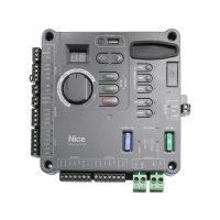
BlueBUS = BlueBUS Photo eye inputs
(STEP MODE)
REMOTE INPUT
N.O.
+V
+V
+V
+V
N.O.
N.O.
N.O.
N.O.
N.O.
N.C.
COM
COM
COM
COM
N.O.
COM
N.O.
COM
10K Ω
SAFETY
SENSORS
LOOPS
BlueBUS
+12 VDC
+12 VDC
(OFF in Standby)
+12 VDC
GUARD
STATION
FIRE
DEPT.
Control
N.O.
Control
Control
LOOP 1
(Obstruct)
LOOP 2
(Shadow)
LOOP 3
(Exit)
Motor 1
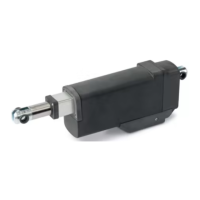
CONNECTIONS
ACTUATOR
Motor 2
SOLAR PANEL or
HIGH CURRENT
DC POWER
BATTERY
12 DC
+
+
_
_
+12 VDC
(OFF
in Standby)
ALARM
COM
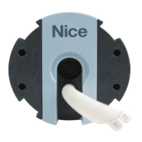
Example: Nice
BlueBUS Photo Eyes
Table of BlueBUS Jumper Settings
10.3.1 BlueBUS Intallation
Installing BlueBUS photo eye sensors:
1. Remove power sources from controller (battery and DC/Solar inputs).
2. Install photo eye pairs in appropriate locations (see gate diagram on next page).
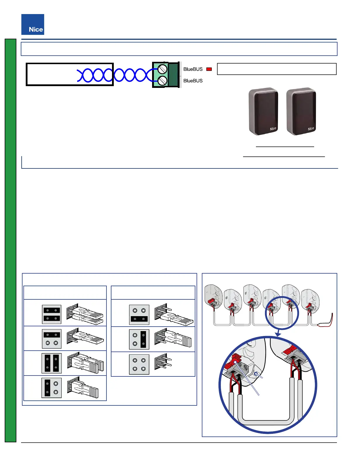
3. Wire BlueBUS photo eyes as shown in example below.
4. Set jumpers of each pair of photo eyes (P1 - P6). Refer to table below and gate diagram on next page.
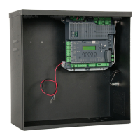
5. Route sensor wires into control box and install sensor wires to BlueBUS input (no polarity required).
6. Reapply power to the controller.
7. At power-up, sensor inputs are scanned, and If BlueBUS detected, sensors are registered & red LED lights.
8. Test function of each sensor by interrupting the infrared beam while the gate is opening or closing.
P1
Close-Direction Open-Direction
P5
P2
P6
P3
P4
Not
Used
BlueBUS Wiring Example
RX
RX RX
TX TX TX
Example
Jumper
Position
Jumper
Sorage
Mercury 310
www.ApolloGateOpeners.com | (800) 878-7829 | Sales@ApolloGateOpeners.com
 Loading...