145
Exchanging Data with the CPU Unit Section 4-5
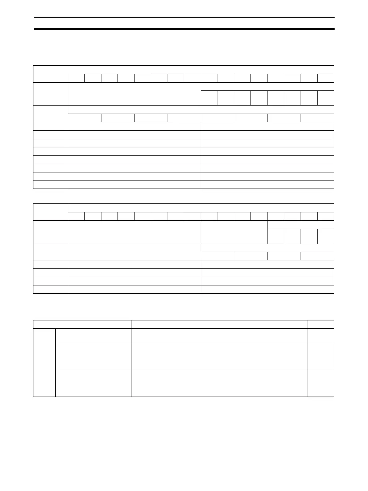
DM Allocation Contents The following table shows the allocation of DM words and bits for both normal
and adjustment mode.
CS1W-DA08V/08C
CS1W-DA041
Note For the DM word addresses, m = D20000 + (unit number x 100).
Set Values and Stored Values]
Note 1. With the CS1W-DA041, the output signal ranges 1 to 5 V and 4 to 20 mA
are switched using the output terminal connections. For details, refer to 4-
4-3 Output Wiring Example. With the CS1W-DA08C, these ranges are in-
valid. Regardless of the settings made, the output range will be 4 to 20 mA.
2. The values output for the signal ranges will be 0 V for the range of
±10 V,
and the minimum value for the other ranges. For details, refer to 4-6-3 Out-
put Hold Function.
DM word Bits
1514131211109876543210
D(m) Not used. Output use setting
Out-
put 8
Out-
put 7
Out-
put 6
Out-
put 5
Out-
put 4
Out-
put 3
Out-
put 2
Out-
put 1
D(m+1) Output signal range setting
Output 8 Output 7 Output 6 Output 5 Output 4 Output 3 Output 2 Output 1
D(m+2) Not used. Output 1: Output status when conversion stopped
D(m+3) Not used. Output 2: Output status when conversion stopped
D(m+4) Not used. Output 3: Output status when conversion stopped
D(m+5) Not used. Output 4: Output status when conversion stopped
D(m+6) Not used. Output 5: Output status when conversion stopped
D(m+7) Not used. Output 6: Output status when conversion stopped
D(m+8) Not used. Output 7: Output status when conversion stopped
D(m+9) Not used. Output 8: Output status when conversion stopped
DM word Bits
1514131211109876543210
D(m) Not used. Not used. Output use setting
Out-
put 4
Out-
put 3
Out-
put 2
Out-
put 1
D(m+1) Not used. Output signal range setting
Output 4 Output 3 Output 2 Output 1
D(m+2) Not used. Output 1: Output status when conversion stopped
D(m+3) Not used. Output 2: Output status when conversion stopped
D(m+4) Not used. Output 3: Output status when conversion stopped
D(m+5) Not used. Output 4: Output status when conversion stopped
Item Contents Page
Output Use setting 0: Not used.
1: Used.
145, 149
Output signal range 00: –10 to 10 V
01: 0 to 10 V
10: 1 to 5 V/4 to 20 mA (See note 1.)
11: 0 to 5 V
145, 149
Output status when stopped 00: CLR Outputs 0 or minimum value of each range.
(See note 2.)
01: HOLD Holds output just before stopping.
02: MAX Outputs maximum value of range.
151
 Loading...


