178
Operating Procedure Section 5-2
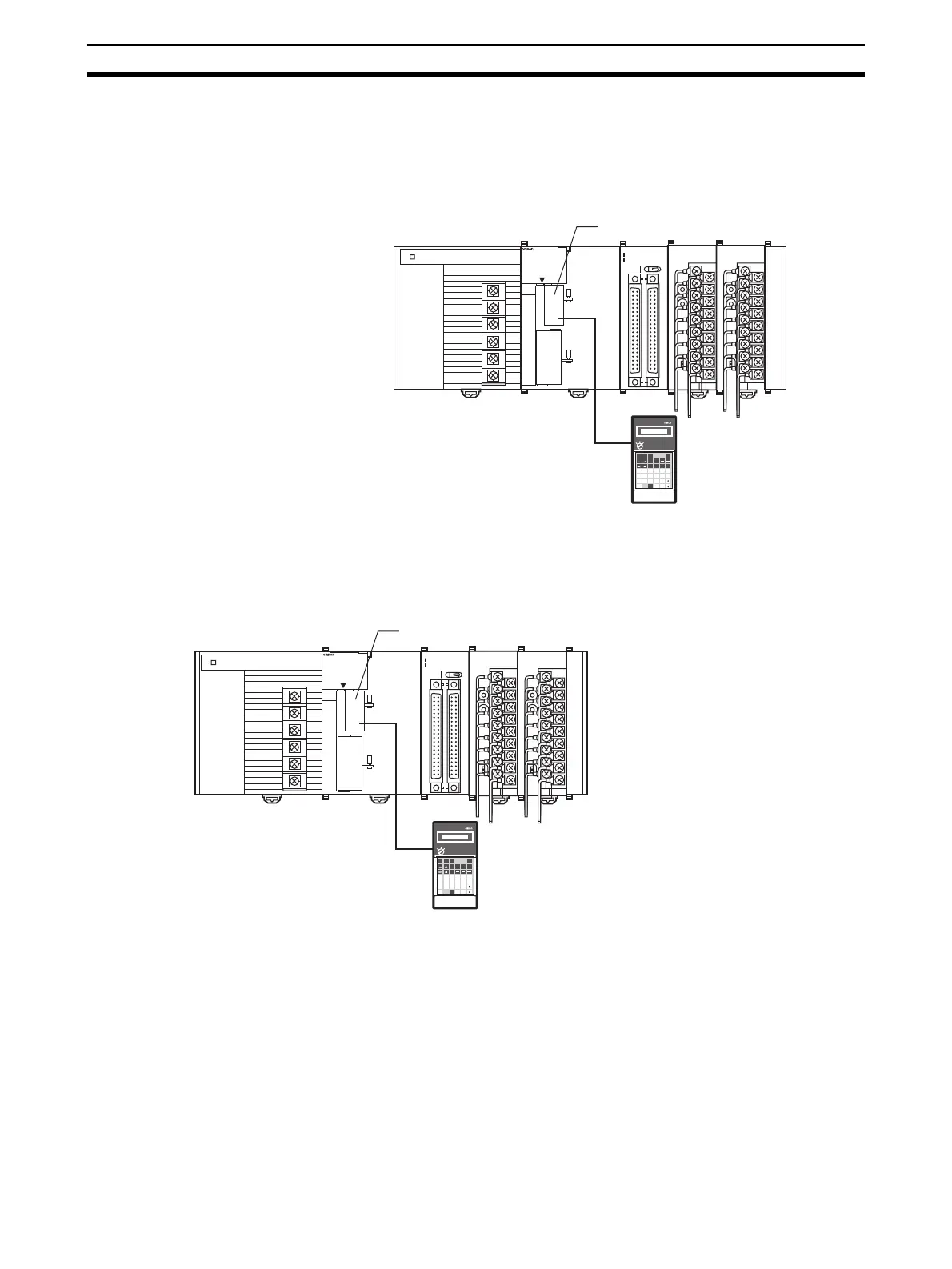
4. Turn ON the power to the PLC.
5. Turn ON the power to the external devices. (Can be turned ON at the same
time as the PLC.)
Creating I/O Tables
After turning ON the power to the PLC, be sure to create the I/O tables.
Initial Data Settings
1,2,3... 1. Specify the Special I/O Unit DM Area settings. Refer to DM Allocation Con-
tents on page 190 for further details.
OD261
SYSMAC
CJ1G-CPU44
PROGRAMMABLE
CONTROLLER
RUN
ERR/ALM
INH
PRPHL
COMM
OPEN
PERIHERAL
PORT
MCPWR
BUSY
01234567
8 9 10 11 12 13 14 15
20
1
CN1
DC24V 0.3A
1
20
CN2
B/A A
/B
0
1
2
3
01234567
8 9 10 11 12 13 14
15
AD081
B1 A1
MACH
No.
x10
1
x10
0
RUN
ERC
ERH
ADJ
MODE
12
DA041
B1 A1
MACH
No.
x10
1
x10
0
RUN
ERC
ERH
ADJ
MODE
12
Peripheral port
Programming Console
OD261
SYSMAC
CJ1G-CPU44
PROGRAMMABLE
CONTROLLER
RUN
ERR/ALM
INH
PRPHL
COMM
OPEN
PERIHERAL
PORT
MCPWR
BUSY
01234567
8 9 10 11 12 13 14 15
20
1
CN1
DC24V 0.3A
1
20
CN2
B/A A
/B
0
1
2
3
01234567
8 9 10 11 12 13 14
15
AD081
B1 A1
MACH
No.
x10
1
x10
0
RUN
ERC
ERH
ADJ
MODE
12
DA041
B1 A1
MACH
No.
x10
1
x10
0
RUN
ERC
ERH
ADJ
MODE
12
Analog input 1: 1 to 5 V
Analog input 2: 1 to 5 V
Analog input 3: 4 to 20 mA
Analog input 4: 4 to 20 mA
Programming Console
Peripheral port
 Loading...


