179
Operating Procedure Section 5-2
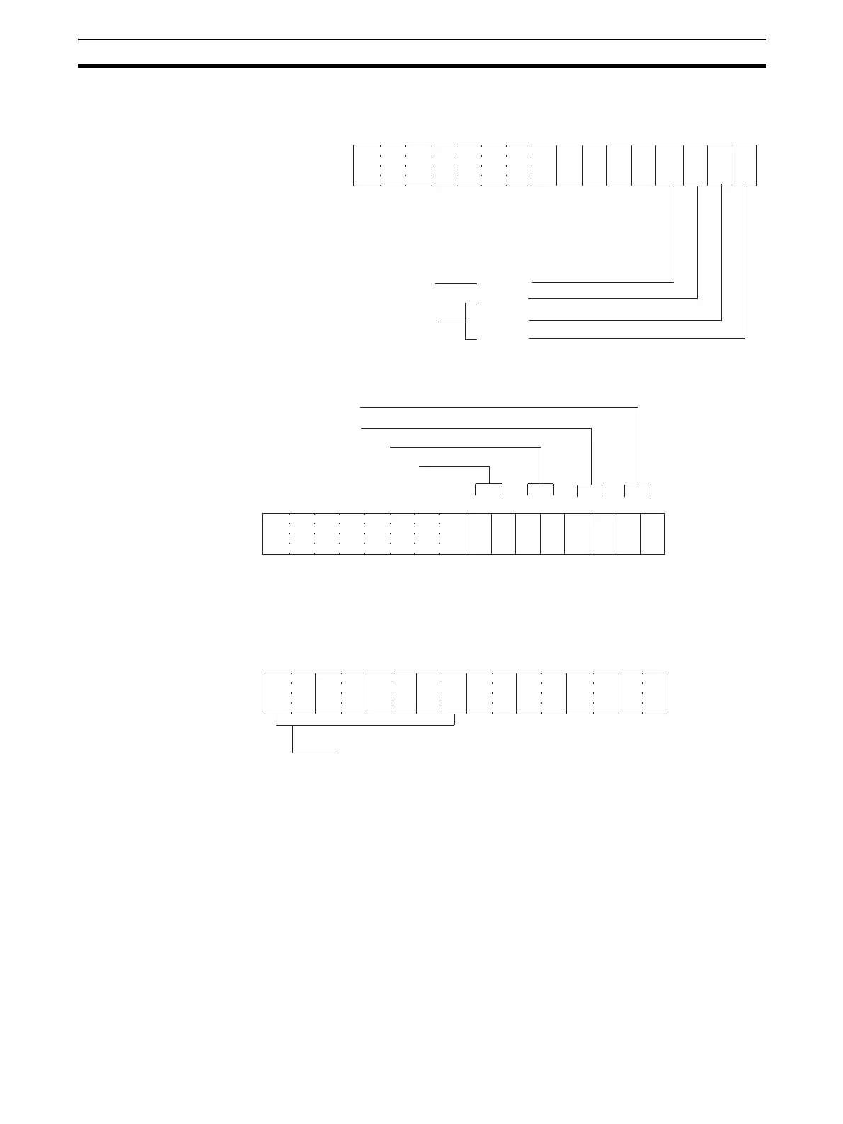
• The following diagram shows the output settings used. Refer to 5-6-1
Output Settings and Conversions for more details.
• The following diagram shows the output range settings. Refer to 5-6-1
Output Settings and Conversions for more details.
Note The output range setting is not required for the CJ1W-DA08C.
• The following diagram shows the conversion time/resolution setting for
the DA08V. (Refer to
5-6-2 Conversion Time/Resolution Setting
(CJ1W-DA08V/08C Only)
.)
2. Turn OFF the external power supply.
3. Restart the CPU Unit.
4. Turn ON the external power supply.
15 14 13 12 11 10 09 08 07 06 05 01 0004 03 02
0 0 0 0 0 0 0 0 0 0 0 0 0 1 1 1
Bit
Not used Output 4
Output 3
Output 2
Output 1
Used
m: DM20100
(0007 Hex)
15 14 13 12 11 10 09 08 07 06 05 01 0004 03 02
0 0 0 0 0 0 0 0 0 0 0 0 1 0 1 0
Bit
m+1: DM20101
(000A Hex)
Output 1: 1 to 5 V. Set to 10.
Output 2: 1 to 5 V. Set to 10.
Output 3: –10 to 10 V. Set to 00.
Output 4: Not used. Set to 00 (disabled).
15 14 13 12 11 10 09 08 07 06 05 01 0004 03 02
0 0 0 0 0 0 0 0
Bit
m+18: D20118
(0000 Hex)
Conversion Time/Resolution Setting
0000: 1-ms conversion time, 4,000 resolution
C100: 250-
µs conversion time, 8,000 resolution
 Loading...


