234
Operating Procedure Section 6-2
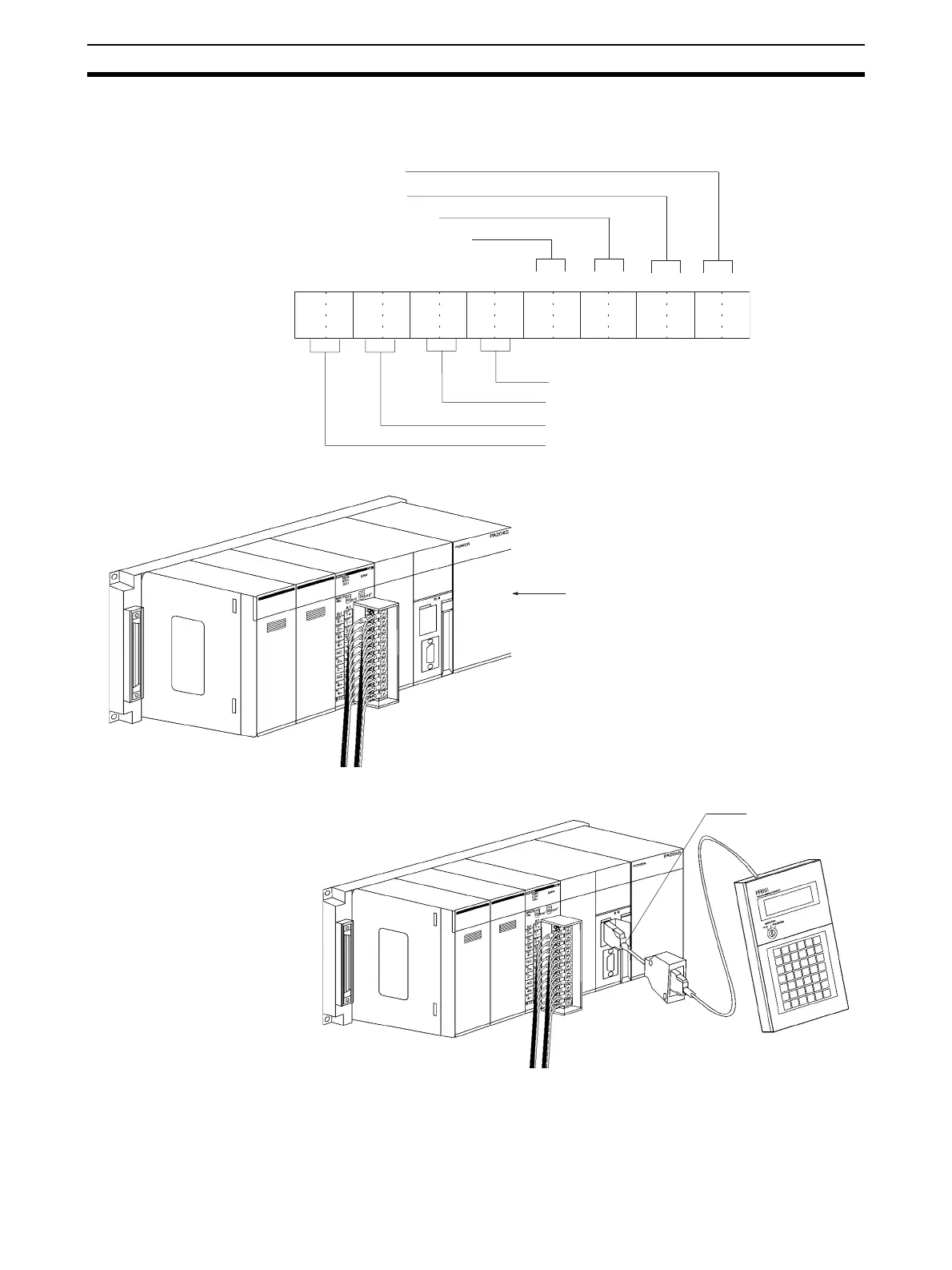
• The following diagram shows the input and output range settings. Re-
fer to 6-6-1 Input Settings and Conversion Values or 6-7-1 Output Set-
tings and Conversions for more details.
2. Restart the CPU Unit.
Creating Ladder Programs
1,2,3... 1. The following example describes how to use analog inputs.
The data that is converted from analog to digital and output to CIO words (n +
5) to (n+ 8) of the Special I/O Unit Area (CIO 2015 to CIO2018), is stored in
the specified addresses D00100 to D00103 as signed binary values 0000 to
0FA0 Hex.
15 14 13 12 11 10 09 08 07 06 05 01 0004 03 02
1 0 1 0 0 1 1 0 0 0 0 0 1 0 1 0
Bit
m+1: DM20101
(A60A Hex)
Output 1: 1 to 5 V. Set to 10.
Output 2: 1 to 5 V. Set to 10.
Output 3: –10 to 10 V. Set to 00.
Output 4: Not used. Set to 00 (disabled).
Input 1: 1 to 5 V. Set to 10.
Input 2: 0 to 10 V. Set to 01.
Input 3: 4 to 20 mA. Set to 10.
Input 4: 4 to 20 mA. Set to 10.
Power turned ON again
(or Special I/O Unit Restart Bit is turned ON)
Peripheral port
 Loading...


