EasyManua.ls Logo

Omron CS1W-AD081-V1 User Manual

Omron CS1W-AD081-V1
427 pages
To Next Page IconTo Next Page
To Previous Page IconTo Previous Page
Page #258 background imageLoading...
Page #258 background image
235
Operating Procedure Section 6-2
The following table shows the addresses used for analog input.
Note a) The addresses are set according to the unit number of the Special
I/O Unit. Refer to 6-3-2 Unit Number Switch for further details.
b) Set as required.
c) The input Disconnection Detection Flag is allocated to bits 04 to
07 of word (n+9). Refer to Allocations for Normal Mode on
page 250 and 6-6-4 Input Disconnection Detection Function for
further details.
2. The following example shows how to use analog outputs.
The setting address D00200 is stored in words (n+1) to (n+3) of the Special I/
O Unit Area (CIO 2011 to CIO 2013) as a signed binary value between 0000
to 0FA0 Hex.
The following table shows the addresses used for analog output.
Input number Input signal range Input conversion
value address
(n = CIO 2010)
(See note 1.)
Conversion data
holding address
(See note 2.)
1 1 to 5 V (n+5) = CIO 2015 D00100
2 0 to 10 V (n+6) = CIO 2016 D00101
3 4 to 20 mA (n+7) = CIO 2017 D00102
4 4 to 20 mA (n+8) = CIO 2018 D00103
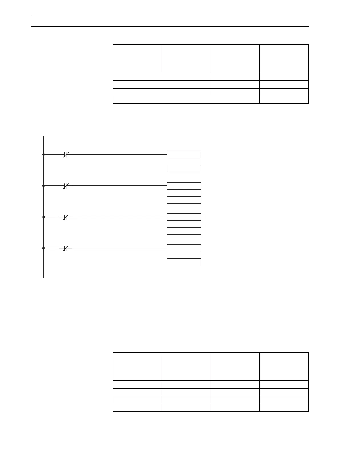
201904 Input 1 Disconnection Detection Flag (See note c.)
201905 Input 2 Disconnection Detection Flag (See note c.)
201906 Input 3 Disconnection Detection Flag (See note c.)
201907 Input 4 Disconnection Detection Flag (See note c.)
For 1 to 5 V, the hexadecimal value 0000
to 0FA0 will be stored in CIO 2015, so if
there is no disconnection (i.e., 201904 is
OFF), CIO 2015 will be stored in
D00100.
In the same way, for 0 to 10 V, CIO 2016
will be stored in D00101.
In the same way, for 4 to 20 mA, CIO 2017
will be stored in D00102.
In the same way, for 4 to 20 mA, CIO 2018
will be stored in D00103.
MOV (021)
2015
D00100
MOV (021)
2016
D00101
MOV (021)
2017
D00102
MOV (021)
2018
D00103
Output number Input signal range Output setting
address
(n = CIO 2010)
See note 1.
Original
conversion
address
1 1 to 5 V (n+1) = CIO 2011 D00200
2 0 to 10 V (n+2) = CIO 2012 D00201
3 –10 to 10 V (n+3) = CIO 2013 D00202
4 Not used. --- ---

Table of Contents

Questions and Answers:

Omron CS1W-AD081-V1 Specifications

General IconGeneral
Number of Channels8
Power Supply5 V DC
Operating Temperature0 to 55 °C
TypeAnalog Input
Input Range0 to 10 V, 0 to 20 mA, 4 to 20 mA
Sampling Time/Conversion Time1ms per channel
Current Consumption100 mA
IsolationPhotocoupler isolation between input and internal circuit
Storage Temperature-25 to 65 °C
Relative Humidity35 to 85% (with no condensation)
Noise Immunity±2 kV
StandardsCE, UL

Summary

SYSMAC CS/CJ Series

Analog I/O Units

Describes the types of analog I/O units covered in the manual, including input, output, and combined units.

PRECAUTIONS

General Precautions

Fundamental safety and operational guidelines for using OMRON products.

Safety Precautions

Critical safety warnings and procedures to prevent injury or damage.

Application Considerations

SECTION 2 CS-series Analog Input Units

2-2 Operating Procedure

Step-by-step instructions for operating CS-series Analog Input Units.

2-6 Analog Input Functions and Operating Procedures

Details on analog input functions and their operational procedures.

2-8 Handling Errors and Alarms

Troubleshooting guide for errors and alarms in Analog Input Units.

SECTION 3 CJ-series Analog Input Units

3-2 Operating Procedure

Step-by-step instructions for operating CJ-series Analog Input Units.

3-6 Analog Input Functions and Operating Procedures

Details on analog input functions and their operational procedures.

3-8 Handling Errors and Alarms

Troubleshooting guide for errors and alarms in Analog Input Units.

SECTION 4 CS-series Analog Output Units

4-2 Operating Procedure

Step-by-step instructions for operating CS-series Analog Output Units.

4-6 Analog Output Functions and Operating Procedures

Details on analog output functions and their operational procedures.

4-8 Handling Errors and Alarms

Troubleshooting guide for errors and alarms in Analog Output Units.

SECTION 5 CJ-series Analog Output Unit

5-2 Operating Procedure

Step-by-step instructions for operating CJ-series Analog Output Units.

5-6 Analog Output Functions and Operating Procedures

Details on analog output functions and their operational procedures.

5-8 Handling Errors and Alarms

Troubleshooting guide for errors and alarms in Analog Output Units.

SECTION 6 CS-series Analog I/O Unit

6-2 Operating Procedure

Step-by-step instructions for operating CS-series Analog I/O Units.

6-6 Analog Input Functions and Operating Procedures

Details on analog input functions and their operational procedures.

6-7 Analog Output Functions and Operating Procedures

Details on analog output functions and their operational procedures.

6-10 Handling Errors and Alarms

Troubleshooting guide for errors and alarms in Analog I/O Units.

SECTION 7 CJ-series Analog I/O Unit

7-2 Operating Procedure

Step-by-step instructions for operating CJ-series Analog I/O Units.

7-6 Analog Input Functions and Operating Procedures

Details on analog input functions and their operational procedures.

7-7 Analog Output Functions and Operating Procedures

Details on analog output functions and their operational procedures.

7-10 Handling Errors and Alarms

Troubleshooting guide for errors and alarms in Analog I/O Units.

Appendix B Sample Programs

Appendix C Data Memory Coding Sheets

Related product manuals