50
Exchanging Data with the CPU Unit Section 2-5
Allocation for Adjustment
Mode
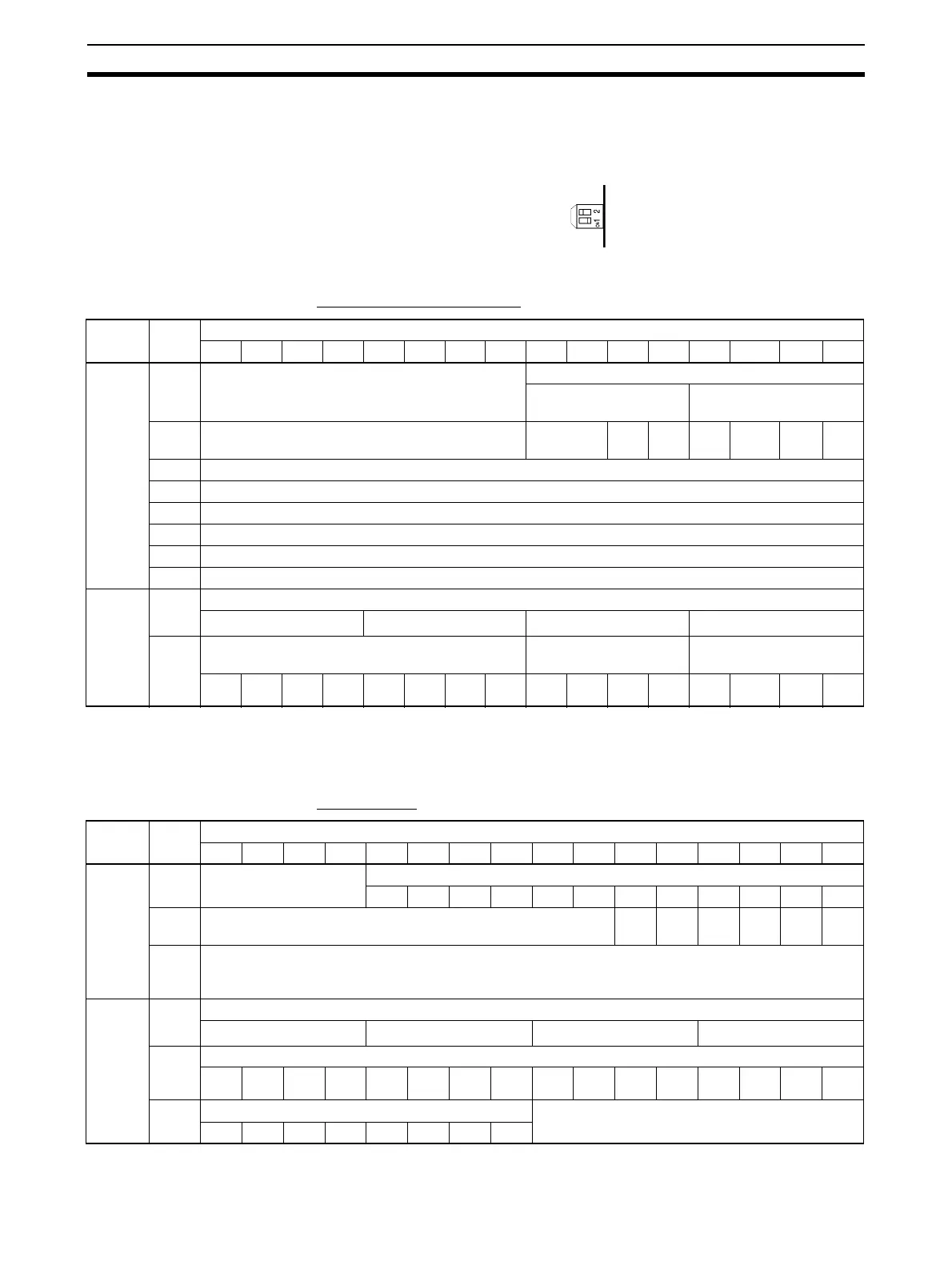
For adjustment mode, turn ON the operation mode switch on the rear panel of
the Unit as shown in the following diagram, or set bits 00 to 07 in DM word
m+18 (m+19 for CS1W-AD161) to C1. When the Unit is set for adjustment
mode, the ADJ indicator on the front panel of the Unit will flash.
The allocation of CIO words and bits is shown in the following table.
CS1W-AD041-V1/AD081-V1
Note 1. Use settings 1 to 4 for the CS1W-AD041-V1.
2. With the CS1W-AD041-V1, bits 04 to 07 in word n+9 (disconnection detec-
tion) are not used.
CS1W-AD161
Note 1. For the CIO word addresses, n = CIO 2000 + unit number x 10.
I/O Word Bits
1514131211109876543 2 10
Output
(CPU to
Unit)
n Not used. Inputs to be adjusted
2 (fixed) 1 to 8 (1 to 4) (See note
1.)
n + 1 Not used. Not used. Clr Set Up Down Gain Off-
set
n + 2 Not used.
n + 3 Not used.
n + 4 Not used.
n + 5 Not used.
n + 6 Not used.
n + 7 Not used.
Input
(Unit to
CPU)
n + 8 Conversion value at time of adjustment
16
3
16
2
16
1
16
0
n + 9 Alarm Flags Disconnection detec-
tion (See note 2.)
Not used.
Input
8
Input
7
Input
6
Input
5
Input
4
Input
3
Input
2
Input
1
I/O Word Bits
1514131211109876543210
Output
(CPU to
Unit)
n Not used. Inputs to be adjusted (See note 2.)
n + 1 Not used. Clr Set --- --- Gain Off-
set
n + 2
to
n+16
Not used.
Input
(Unit to
CPU)
n + 17 Conversion value at time of adjustment
16
3
16
2
16
1
16
0
n + 18 Disconnection detection
Input
16
Input
15
Input
14
Input
13
Input
12
Input
11
Input
10
Input
9
Input
8
Input
7
Input
6
Input
5
Input
4
Input
3
Input
2
Input
1
n + 19 Alarm Flags Not used.
 Loading...


