51
Exchanging Data with the CPU Unit Section 2-5
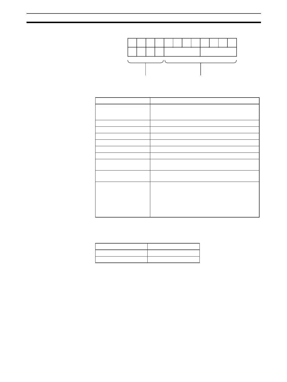
2. The input format used for adjustment is as follows:
Set Values and Stored
Values
Refer to 2-7-1 Adjustment Mode Operational Flow for further details.
Note For the CIO word addresses, n = CIO 2000 + (unit number x 10).
The input disconnection detection function can be used when the input signal
range is set for 1 to 5 V (4 to 20 mA).
11 10 09 08 07 06 05 04 03 02 01 00
0 0 1 0 10
1
10
0
Bit
Always 2 Hex Number of input for adjustment:
1 to 16 (BCD)
Item Contents
Input to be adjusted Sets input to be adjusted.
Leftmost digit: 2 (fixed)
Rightmost digit: 1 to 8 (1 to 4 for CS1W-AD041-V1)
Offset (Offset Bit) When ON, adjusts offset error.
Gain (Gain Bit) When ON, adjusts gain error.
Down (Down Bit) Decrements the adjustment value while ON.
Up (Up Bit) Increments the adjustment value while ON.
Set (Set Bit) Sets adjusted value and writes to EEPROM.
Clr (Clear Bit) Clears adjusted value. (Returns to default status)
Conversion value for
adjustment
The conversion value for adjustment is stored as 16 bits
of binary data.
Disconnection detection 0: No disconnection
1: Disconnection
Alarm Flags Bit 12: Input value is outside adjustment limits
(in adjustment mode)
Bit 13: Input number setting error
(in adjustment mode)
Bit 14: EEPROM write error (in adjustment mode)
Bit 15: Operating in adjustment mode
(always 1 in adjustment mode)
Input signal range Voltage/current
1 to 5 V 0.3 V max.
4 to 20 mA 1.2 mA max.
 Loading...


