Controlling Operation and Outputting Data with PLC Link Communications
FQ2-S/CH User’s Manual
for Communications Settings
129
3
Controlling Operation and Outputting Data with an
Ethernet Connection
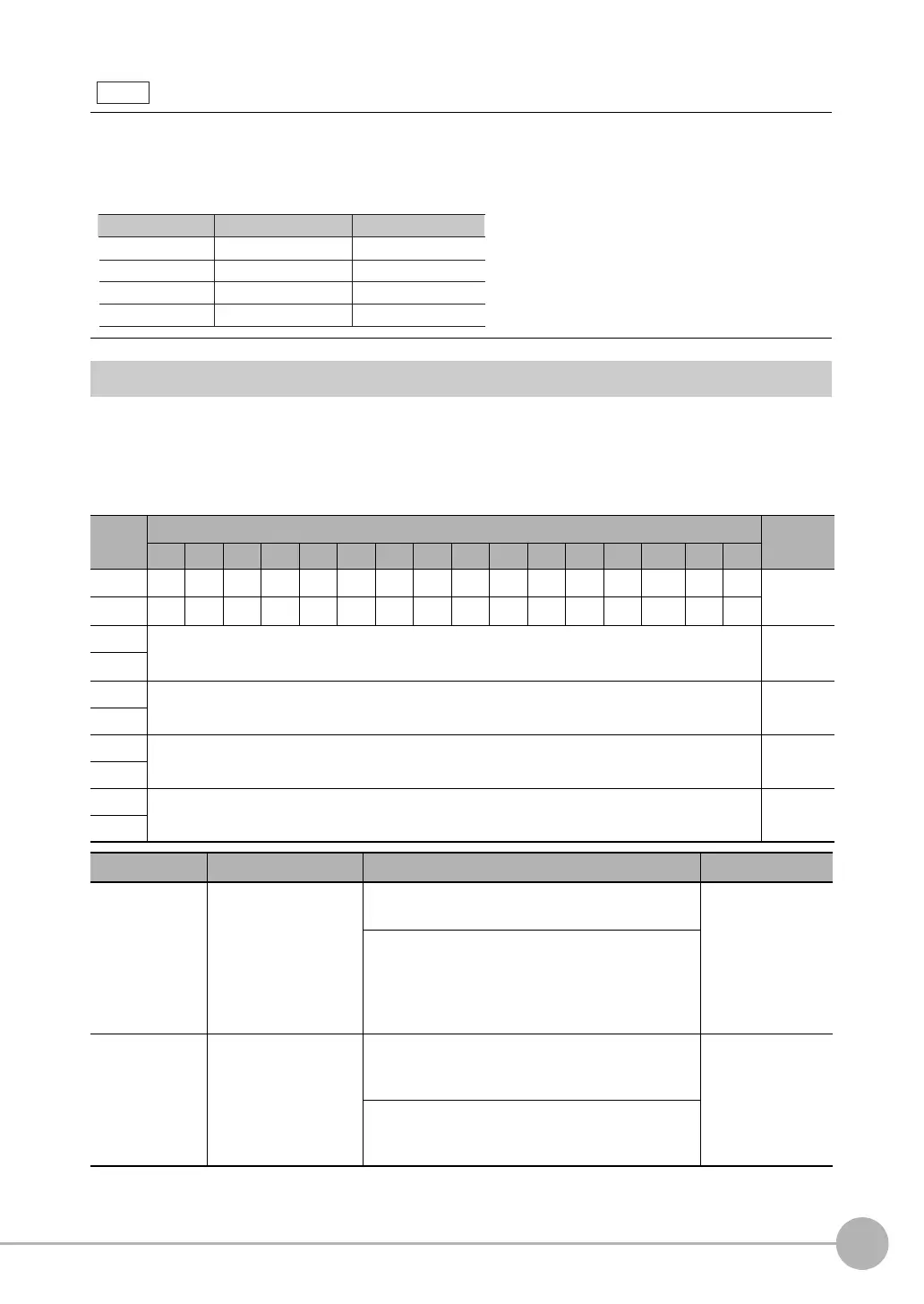
Memory Assignments for PLC Link Communications
This section describes the assignments for the Command, Response, and Data Output Areas.
● Command Area
PLC (Master) to Vision Sensor (Slave)
• Endian
Little endian data is output.
• Code Conversion
The converted codes are outputted for the following character codes.
First
word
Bits Contents
15 14 13 12 11 10 9 8 7 6 5 4 3 2 1 0
+0
ERRCLR
Resv Resv Resv Resv Resv Resv Resv Resv Resv Resv Resv Resv Resv Resv EXE Control sig-
nals (32
bits)
+1 Resv Resv Resv Resv Resv Resv Resv Resv Resv Resv Resv Resv Resv Resv Resv
DSA
+2 Command code Command
code (32
bits)
+3
+4 Parameter 1 Parameter
(integer)
+5
+6 Parameter 2 Spare (inte-
ger)
+7
+8 Parameter 3 Spare (inte-
ger)
+9
Signal Signal name Function Application
EXE Control Command
Execution Bit
Turn ON this signal from the PLC to send a control
command for the Vision Sensor to execute.
Command/
response commu-
nications
Turn OFF the EXE signal from the PLC when the
Control Command Completed (FLG) signal from the
Vision Sensor turns ON. (Set the control command
code and parameters before you turn ON this sig-
nal.)
DSA Data Output Request
Bit
Turn ON this signal from the PLC to request data
output. When this signal turns ON, the Vision Sen-
sor outputs data.
Data output after
measurements
Turn OFF the DSA signal from the PLC when the
Data Output Completed (GATE) signal from the
Vision Sensor turns ON.
CR
Before conversion After conversion
LF
&h0D
&h7F
&h8541
DEL
&h8543
Character code
&h0A
&hFF
&h8542
&h8544
FF
FQ2-S_CH_comm.book 129 ページ 2014年6月26日 木曜日 午前11時47分

 Loading...


