Controlling Operation and Outputting Data with the Sensor's Standard Parallel Connection
36
FQ2-S/CH User’s Manual
for Communications Settings
Setting the Measurement Trigger
The measurement trigger can be chosen from the following two types:
• One-shot measurement: One measurement is performed for each external trigger.
• Continuous measurement: Measurements are performed continuously.
Performing One Measurement for Each External Trigger
A measurement trigger is input as the TRIG signal from a proximity sensor, PLC, or other external device.
One measurement is performed when the TRIG signal turns ON.
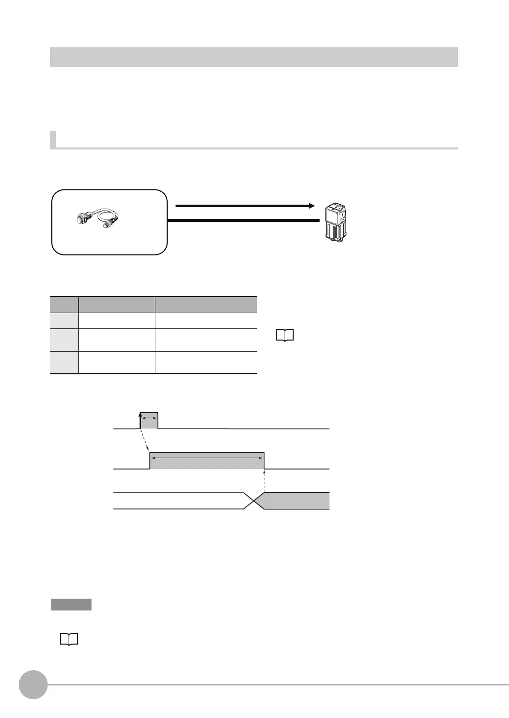
Wiring
Timing Chart
1. Turn ON the TRIG signal while the BUSY signal is OFF.
2. Measurement begins and the BUSY signal is turned ON during the measurement process.
3. When the measurement has been finished, the measurement result is output using an OR signal, and the
BUSY signal is turned OFF.
*1
*1: You can also set the signal to be turned OFF after data logging, image logging, or displaying results in the [BUSY output].
When the Brightness Correction Mode is ON, the timing when images are taken is delayed.
Section 3 Taking Images
in Vision Sensor FQ2-S/CH Series User's Manual (Cat. No. Z337)
Color Signal Description
The signals shown at the left are used.
Refer to the following information for signal wiring.
Section 2 Installation and Connections
in Vision Sensor FQ2-S/CH Series
User's Manual (Cat. No. Z337)
Pink TRIG Trigger signal
Black OUT0 (OR) Overall judgement (default
assignment)
Orange OUT1 (BUSY) Processing in progress (default
assignment)
(2) Performs
measurements once
Trigger input Sensor
Or other
device
(1) TRIG signal ON
OFF
ON
OFF
ON
Turned ON when overall judgement is NG.
(OR output: ON for NG)
OR signal
ON while measurements are
being processed (depends
on BUSY output conditions)
BUSY signal
TRIG signal
ON for 1 ms min.
FQ2-S_CH_comm.book 36 ページ 2014年6月26日 木曜日 午前11時47分

 Loading...


