Outputting Data and Controlling Operation through PROFINET
FQ2-S/CH User’s Manual
for Communications Settings
165
3
Controlling Operation and Outputting Data with an
Ethernet Connection
Set the parameters so that the following conditions are met for the data output period and time.
• Set the data output period so that it is longer that the GATE signal ON period and shorter than the measurement
interval of the Sensor.
• Set the “GATE signal output time” to a longer time than the PLC cycle time and the “PROFINET communication
cycle”.
• When operating under high-load conditions, a considerable leeway is required in the measurement interval to
enable stable communications.
• On a network to which many devices are connected, performance may drop (e.g., responses may be delayed or
packets lost) or communications errors may occur when there is temporarily high traffic on the network. Test the
operation under actual conditions before you start actual operation of the system.
• If the measurement interval is short, communications errors may occur depending on the measurement processing
time of the Sensor and the settings in the PLC. Set the timeout time in the connection settings
*1
so that it is longer
than the measurement processing time of the Sensor or increase the measurement interval.
*1 These are the connection settings for tag data links. Make these settings from the Network Configurator.
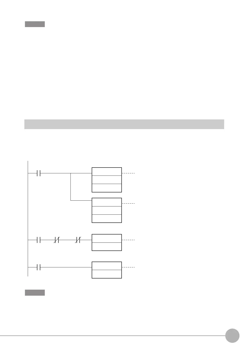
Sample Ladder Programming
● Command/Response Communications
The following sample program is used to clear measurement values.
The Clear Measurement Values command (lower bytes: #2010, upper bytes: #0010) is sent to the Vision
Sensor.
Create the ladder program to control the TRIG signal so that it does not turn ON while the BUSY signal is ON. If not, a
TRIG input error will occur and the ERROR signal will turn ON.
Sets the lower word of the Clear
Measurement Values command.
The address varies depending
on the PLC that is used.
To specify the address,
refer to the PLC manual.
MOV
#2010
MOV
#0010
SET
RSET
Sets the upper word of the Clear
Measurement Values command.
The address varies depending
on the PLC that is used.
To specify the address,
refer to the PLC manual.
First RUN
Period Flag
Control Command
Completed (FLG)
Execution
condition
Control Command
Completed (FLG)
Turns ON Command Execution Bit.
When the control command is completed,
the Command Execution Bit is turned OFF.
Command Execution
Active (BUSY)
+4 area (area that is
4 words from the +0 area)
+5 area (area that is
5 words from the +0 area)
Command Execution Bit
Command Execution Bit
FQ2-S_CH_comm.book 165 ページ 2014年6月26日 木曜日 午前11時47分