Outputting Data and Controlling Operation through PROFINET
144
FQ2-S/CH User’s Manual
for Communications Settings
FQ2 Communications for PROFINET Connections
You can use PROFINET IO data CR to communicate between the PLC and the Vision Sensor to perform
control via command/response communications or to output data after measurements.
The FQ2 complies with PROFINET conformance class A.
To connect to external devices and communicate using PROFINET, configure the PROFINET IO data CR
settings with the Engineering Tool.
For details on the IO data CR settings in the Engineering Tool, refer to the manual for each Engineering Tool.
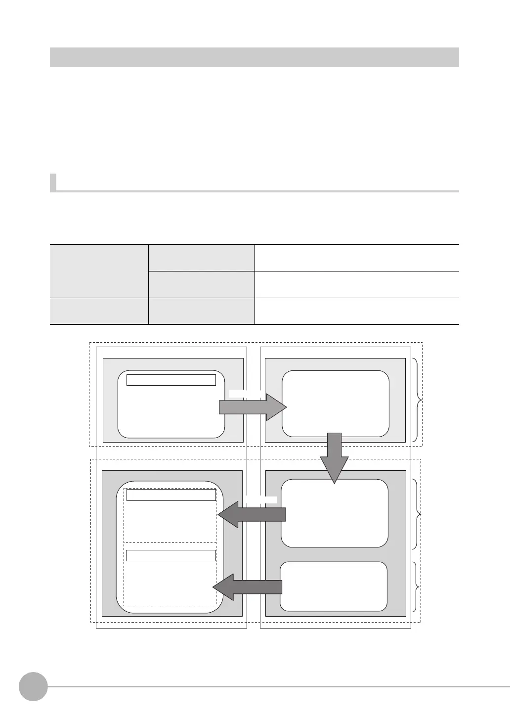
Types of Communications Areas
For PROFINET communications, the following three communications areas are used in the PLC to perform communications.
Areas Used for the Different Control Methods
*1: The Input Area (response area) (2) and Input Area (output area) (3) are assigned to continuous memory addresses or to a variable.
Command/response
communications
(1) Output Area (command
area)
This is the area to which you write control commands for
the Vision Sensor to execute.
(2) Input Area (response
area)
This is the area to which the Vision Sensor writes the results
of control commands executed from the command area.
Data output after mea-
surements
(3) Input Area (output area)
This is the area to which the Vision Sensor writes output
data for measurements after an inspection is performed.
(1) Output Area (command area)
External device
• Control inputs
• Command code
• Command parameters
(2) Input Area (response area)
(3) Input Area (output area)
• Control outputs
• Command code
• Response code
• Response data
• Output data 0 to 64
• Character string to output
Vision Sensor
Execution
After measurements
Output Module
Input Slot
*1
Output Slot
Input Module
Input Module Output Module
20 bytes
16 bytes
32 to
256 bytes
The control commands that are
written to the Command Area
are executed.
Measurement results are
written to the response area
in the PLC.
The execution results
from the Vision Sensor
are written here.
Output data from the
Vision Sensor is written
here.
Measurement results are
written to the output area.
The following control commands
are written to the Vision Sensor.
Input
connection
to Sensor
Output
connection
to PLC
Response
Command
FQ2-S_CH_comm.book 144 ページ 2014年6月26日 木曜日 午前11時47分

 Loading...


