Control Methods Using an External Device
FQ2-S/CH User’s Manual
for Communications Settings
21
1
Overview of Communication Specifications
Memory Areas Used by the Command/Response Control Method
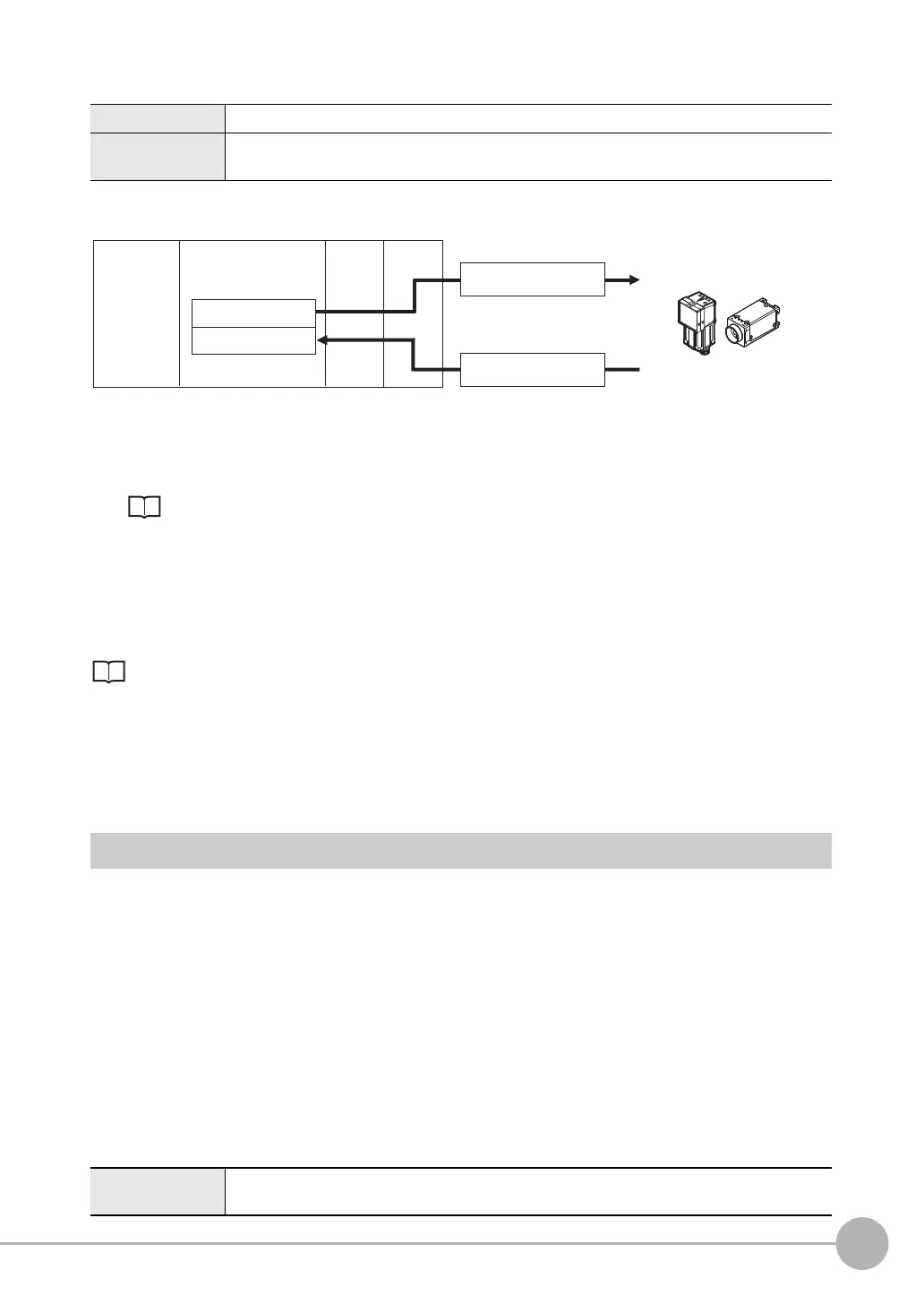
Flow of Communications between the PLC and the Sensor
(1) The PLC (the user) writes a control command to a specified PLC I/O memory area (the Command Area).
Parameter Notation Examples for Command Control: p.200
(2) The PLC (the user) then turns ON the EXE bit to send the control command to the Sensor.
(3) The Sensor executes the received control command.
(4) The Sensor returns a response to the PLC after the control command is executed.
(5) The PLC (the user) stores the response in a specified PLC I/O memory area (the Response Area).
The available control commands depend on the communications protocol that is used.
Command List: p.202.
No-protocol (TCP) Communications, No-protocol (UDP) Communications, No-protocol (FINS/
TCP) Communications
Communications commands are sent to the Sensor through sequence control in the PLC. An external device
and the Sensor communicate through no-protocol communications.
Data Output after Measurements
After a Single Measurement or Start Continuous Measurements command is executed, the Sensor
automatically outputs the data that corresponds to the measurements that have been specified as output items
to the PLC. This allows you to easily pass measurement results data from the inspection items to the PLC. You
can also choose to output only when the PLC meets the conditions that are required to receive the data (i.e.,
when handshaking is turned ON).
The output destination for data depends on the protocol that is used to communicate between the external
device and the Sensor, as described below.
PLC Link, EtherNet/IP, or PROFINET
The output data is automatically output to the following area that is specified PLC I/O memory.
Area of Memory Used for Data Output after Measurement
Command Area You write the control commands to execute for the Sensor to this area.
Response Area You read the results of executing the control commands that were written to the Command Area
from this area.
Data Output Area The output data for the measurement is written to this area by the Sensor after execution of the
measurement.
(1) Command Area
(5) Response Area
(2) Command
(4) Response
PLC
CPU Unit
I/O memory
(communications areas)
• Switch Scene Number
• Single Measurement, etc.
OK, etc.
(3) Command is processed.
Sensor
FQ2-S_CH_comm.book 21 ページ 2014年6月26日 木曜日 午前11時47分

 Loading...


