Controlling Operation and Outputting Data with EtherNet/IP Communications
FQ2-S/CH User’s Manual
for Communications Settings
91
3
Controlling Operation and Outputting Data with an
Ethernet Connection
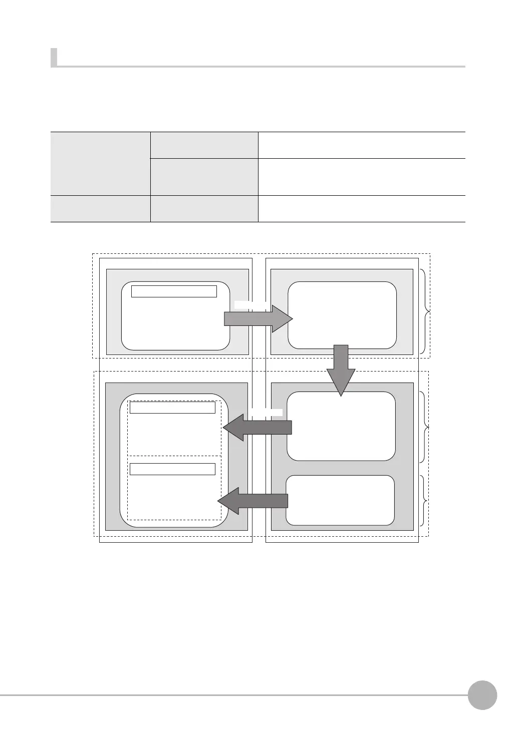
Types of Communications Areas
For EtherNet/IP communications, the following three communications areas are used in the PLC to perform
communications.
Areas Used for the Different Control Methods
*1: The response area (2) and output area (3) are assigned to continuous memory addresses or to a variable.
Command/response
communications
(1) Command area This is the area to which you write control commands for
the Vision Sensor to execute.
(2) Response area This is the area to which the Vision Sensor writes the
results of control commands executed from the command
area.
Data output after measure-
ments
(3) Output area This is the area to which the Vision Sensor writes output
data for measurements after an inspection is performed.
(1) Command area
PLC
• Control inputs
• Command code
• Command parameters
(2) Response area
(3) Output area
• Control outputs
• Command code
• Response code
• Response data
• Output data
• Character string to output
Vision Sensor
Execution
After measurements
Output Tag Set
Input Tags
*1
Output Tags
Input Tag Set
Input Tag Set Output Tag Set
20 bytes
16 bytes
32 to
256 bytes
The control commands that are
written to the Command Area
are executed.
Measurement results are
written to the response area
in the PLC.
The execution results
from the Vision Sensor
are written here.
Output data from the
Vision Sensor is written
here.
Measurement results are
written to the output area.
The following control commands
are written to the Vision Sensor.
Input
connection
to Sensor
Output
connection
to PLC
Response
Command
FQ2-S_CH_comm.book 91 ページ 2014年6月26日 木曜日 午前11時47分

 Loading...


