Controlling Operation and Outputting Data with PLC Link Communications
FQ2-S/CH User’s Manual
for Communications Settings
139
3
Controlling Operation and Outputting Data with an
Ethernet Connection
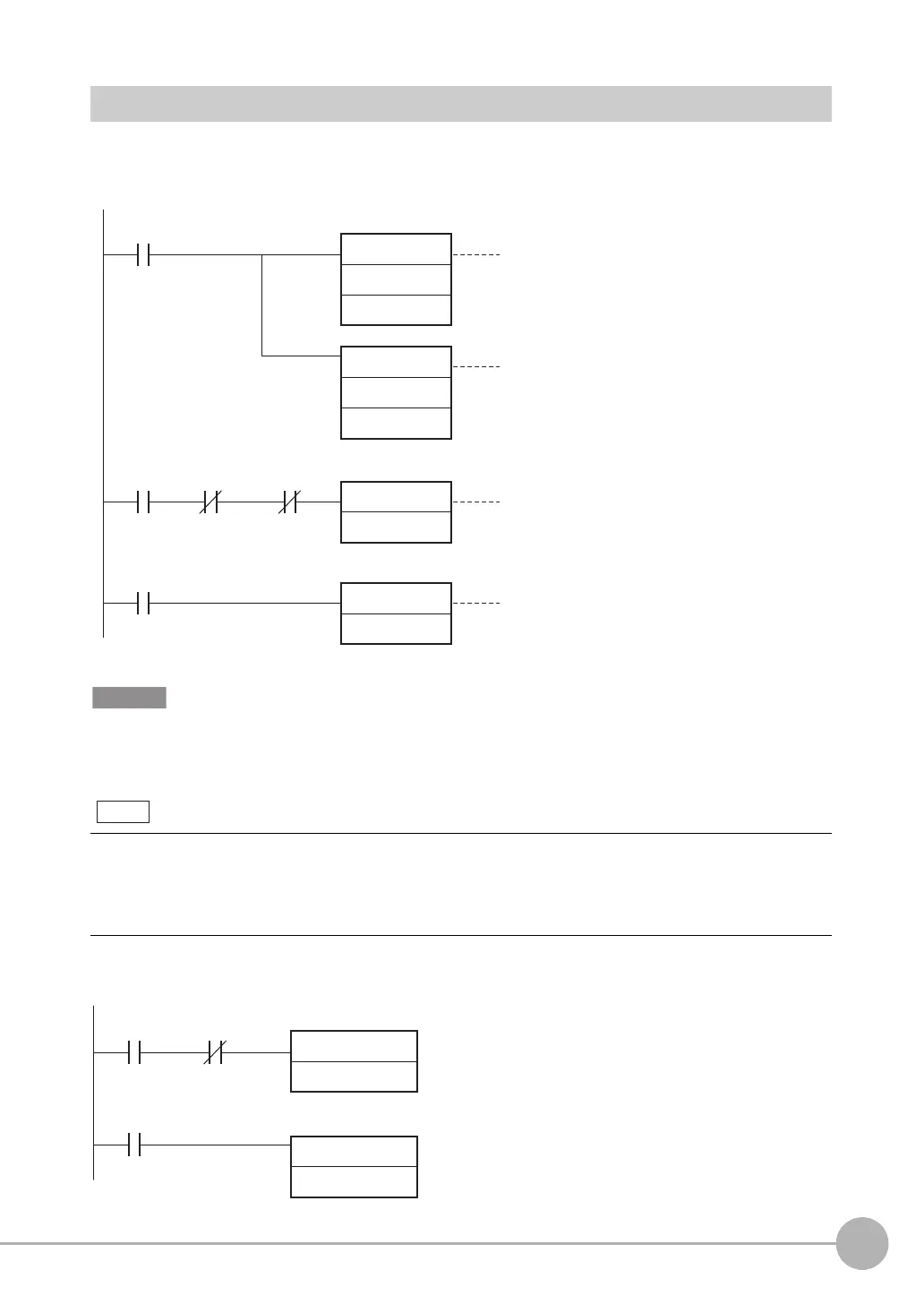
Sample Ladder Programming
● Command/Response Communications
The following sample program is used to perform single measurements. The single measurements command
(lower bytes: #1010, upper bytes: #0010) is sent to the Vision Sensor.
Create the ladder program to control the TRIG signal so that it does not turn ON while the BUSY signal is ON. If not, a
TRIG input error will occur and the ERROR signal will turn ON.
● Data Output after Measurements When Handshaking Is Enabled
You can combine both parallel and PLC Link communications. PLC Link commands cannot be executed while the
Command Execution Active (BUSY) parallel communications signal is ON during execution for the parallel measure-
ment trigger input (TRIG signal). Execute PLC Link commands while the Command Execution Active (BUSY) paral-
lel communications signal is OFF. You can also perform measurements with the measurement trigger input (TRIG
signal) in parallel I/O and use PLC Link communications to output data.
First RUN
Period Flag
Control Command
Completed (FLG)
Execution
condition
Control Command
Completed (FLG)
Sets the lower word of the
measurement command.
Sets the upper word of the
measurement command.
Turns ON Command Execution Bit.
When the control command is completed,
the Command Execution Bit is turned OFF.
Command Execution
Active (BUSY)
MOV
#1010
+2 word
MOV
#0010
+3 word
SET
Command Execution Bit
RSET
Command Execution Bit
Data Output
Completed (GATE)
Execution
condition
Data Output
Completed (GATE)
Data Output Request Bit (DSA)
SET
RSET
Data Output Request Bit (DSA)
FQ2-S_CH_comm.book 139 ページ 2014年6月26日 木曜日 午前11時47分