117
OS32C
User’s Manual
Chapter5
Wiring
E
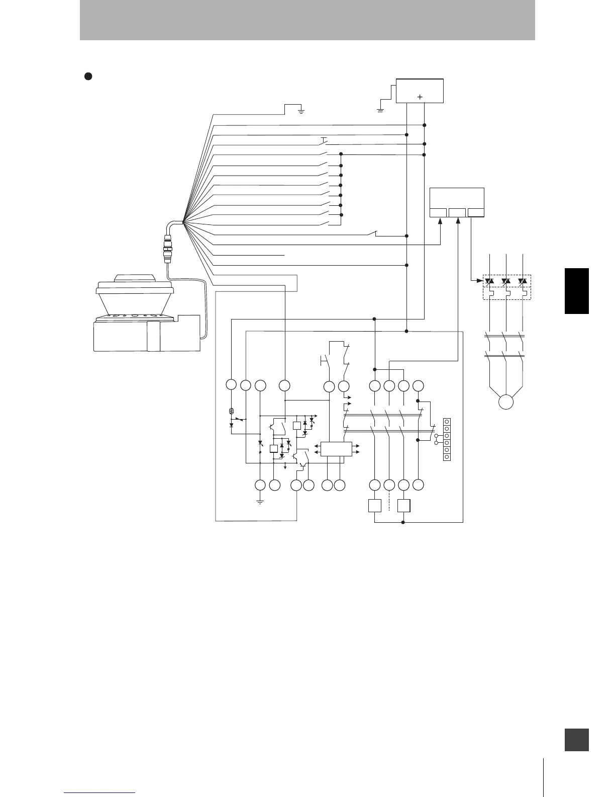
Fig. 5-5 Connecting to the Controller G9SA-301
S2
S4
S2
S1
0VDC (Brown)
Standby input (Violet)
Zone Select 1 (Orange/White)
Zone Select 2 (Orange/Balck)
Zone Select 3 (Gray)
Start (Black)
Auxiliary output(Blue)
Warning output (Red/Black)
EDM (Brown/White) *3
Safety output B (Yellow)
Safety output A (Red)
* 4
Connecting to the controller G9SA-301
Category 3, Performance Level d (ISO13849-1)
Functional Earth (Green)
24VDC (White)
Zone Select 4 (Pink)
Zone Select 5 (White/Black)
S2
S2
S2
Zone Select 6 (Tan)
Zone Select 7 (Orange)
Zone Select 8 (Blue/White)
S2
S2
S2
*1. The External Devices (ED1 & ED2) are force-guided relays. (e.g. G7Z, G7SA or G7S)
*2. The Start Input must be a Normally Closed switch.
*3. If the External Device Monitoring is not used, connect brown/white wires to 0 V,
and then turn OFF the External Device Monitoring with the configuration software.
*4.
ED1, ED2: Forced guided relay
ED3: Solid state contactor (G3J)
M : 3-Phase Motor
S1 : Start Input
(use for releasing lockout)
S2 : Zone Select Switch
S4 :
Standby
Switch
S3 :
Reset Switch
E1 : 24 VDC Power
PLC: Programmable Controller
(This is for monitoring only and
unrelated to a safety system)
M
OUT
PLC
IN1 IN2
ED3
24V
0V
E1
* 4
* 4
* 4
* 4
* 4
* 4
* 4
*1
*1
*2
PE
A1
T23
PE
14
24
34
42
41332313
T32T31
T11
A2
ED1 ED2
ED1
ED2
S3
T12
K1
K2
T21
T22
A B
a
b
2
5
3
4
1
2
3
4
5
6
Control
Circuit
JP
*1
*1
K1
K1
6
a
K2
K2
b
1
For zone select switch setting, see Zone Set Input Selection. When using only one zone,
no connection is needed for the zone select inputs.
 Loading...