25
OS32C
User’s Manual
Chapter2
Operating States & Output Modes
E
Zone Set Switching
Introduction to zone set switching
As an example, examine a system configured to use 4 inputs with 2 of them active according to the
following table:
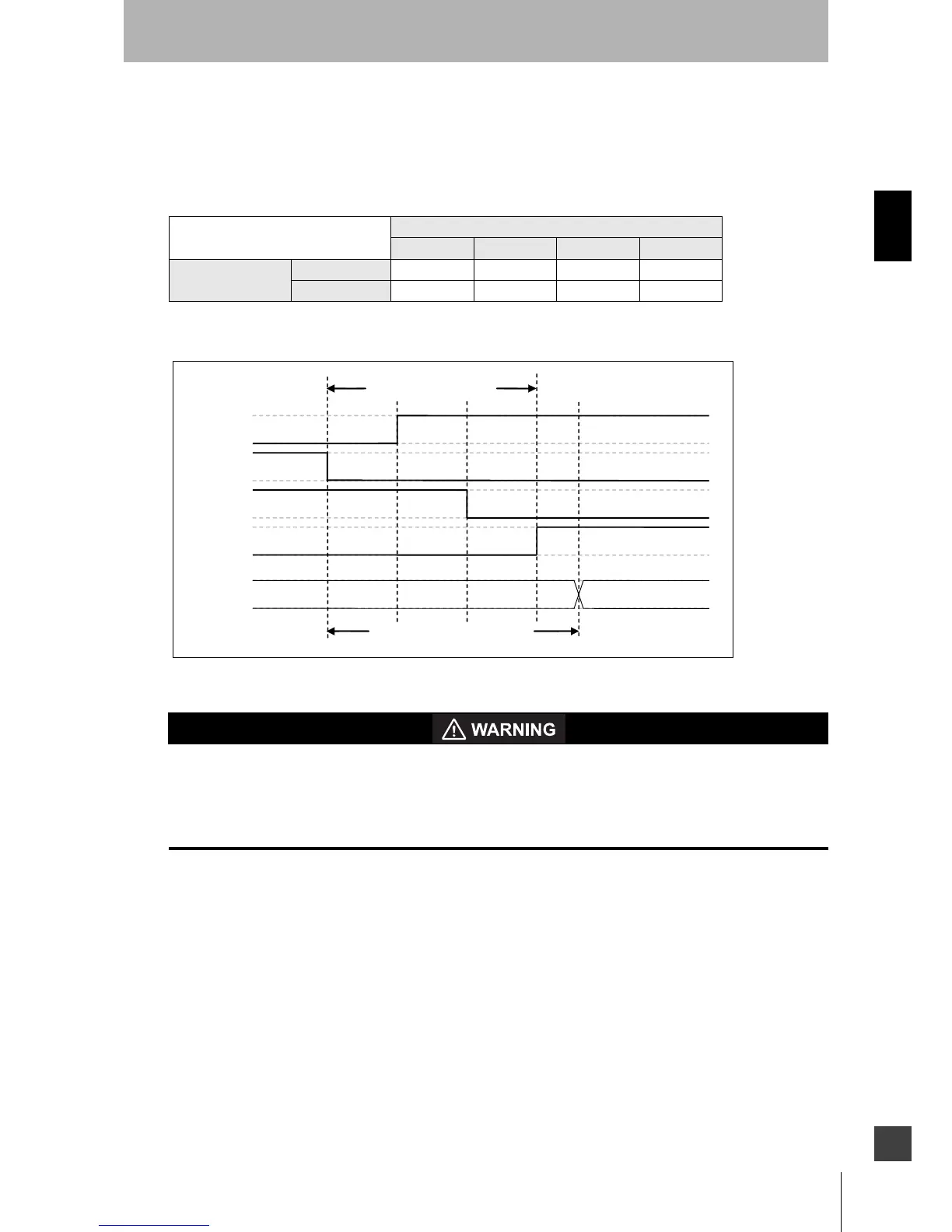
The following figure represents a transition from ZONE 1 to ZONE 2:
Fig. 2-7 Zone Switching example
If the external zone switching device momentarily exceeds the configured number of active zone set
select inputs during the zone switch, an additional Zone Delay may be incurred in the event that wiring
of a zone set select input fails. The external zone switching device must properly sequence so the
configured number of active inputs is not exceeded in order to guarantee that failed zone set select
input wiring will be detected within the normal Zone Switching Time described below.
Let's consider an example Zone set A to Zone set B switching, where A represents any origin zone set
number and B represents any destination zone set number.
When switching zone sets, there are three installation dependent parameters:
1) Zone Set Switching Timing - When switching from Zone set A, there is a point in time when
protection of that zone set is no longer required, this point will be defined as t
EndZoneA. When
transitioning to Zone set B, there is a point in time when the OSSDs must turn OFF if an object is
present in Zone set B, this point will be defined as t
DangerZoneB. In order to ensure, tDangerZoneB is
met, monitoring of Zone set B must start at least one response time (T
response) prior to tDangerZoneB.
The time at which monitoring of Zone set B must start will be defined as t
StartZoneB, where
t
StartZoneB = tDangerZoneB - Tresponse
Zone Set Select Inputs
Z1 Z2 Z3 Z4
Zone Sets
Zone set 1 LOW HIGH HIGH LOW
Zone set 2 HIGH LOW LOW HIGH
 Loading...