116
Chapter5
OS32C
User’s Manual
Wiring
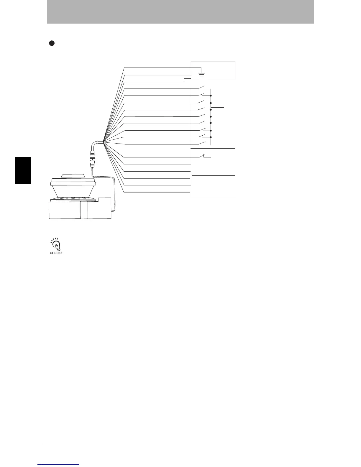
Fig. 5-4 Connecting to AGV Controls
The circuit configuration of the stop/deceleration control must meet the requirements of category 3.
0VDC (Brown)
Standby input (Violet)
Zone Select 1 (Orange/White)
Zone Select 2 (Orange/Black)
Zone Select 3 (Gray)
Auxiliary output(Blue)
Warning output (Red/Black)
EDM (Brown/White)
Safety output B (Yellow)
Safety output A (Red)
Connecting to the AGV Controls
Category 3, Performance Level d (ISO13849-1)
Functional Earth (Green)
24VDC (White)
Zone Select 4 (Pink)
Zone Select 5 (White/Black)
Zone Select 6 (Tan)
Zone Select 7 (Orange)
Zone Select 8 (Blue/White)
OS32C Configuration
- External Device Monitoring Disabled
Automatic Start
Stop/Brake Control
Auxiliary Control
AGV Controls
Zone Control
Power (24VDC)
+24VDC
0VDC
Start (Black)
 Loading...