3-19
3-1 Servo Drive Specifications
OMNUC G5-series AC Servomotors and Servo Drives User’s Manual (with Built-in EtherCAT Communications)
3
Specifications
Monitor Inputs (MON0, MON1, and MON2)
These are the general-purpose monitor inputs.
The general-purpose monitor inputs do not affect operation and can be monitored from the host
controller.
With the default settings, MON0 is allocated to pin 13.
Forward External Torque Limit Input (PCL) and Reverse External Torque Limit Input
(NCL)
Turn ON these inputs to limit the torque to the value set in the Forward External Torque Limit (3525
hex) and the Reverse External Torque Limit (3526 hex).
While the input is ON, operation continues within the torque limit.
With the default settings, the inputs are not allocated.
Backup Battery Inputs (BAT)
Function:
These are the backup battery connection terminals used when the absolute encoder power is
interrupted.
If a battery is connected to the battery holder for the absolute encoder battery cable, do not
connect anything to these terminals.
Precautions for Correct Use
Be sure not to connect to both of the absolute encoder battery cable and the backup battery
inputs at the same time. Such connection may result in malfunction.
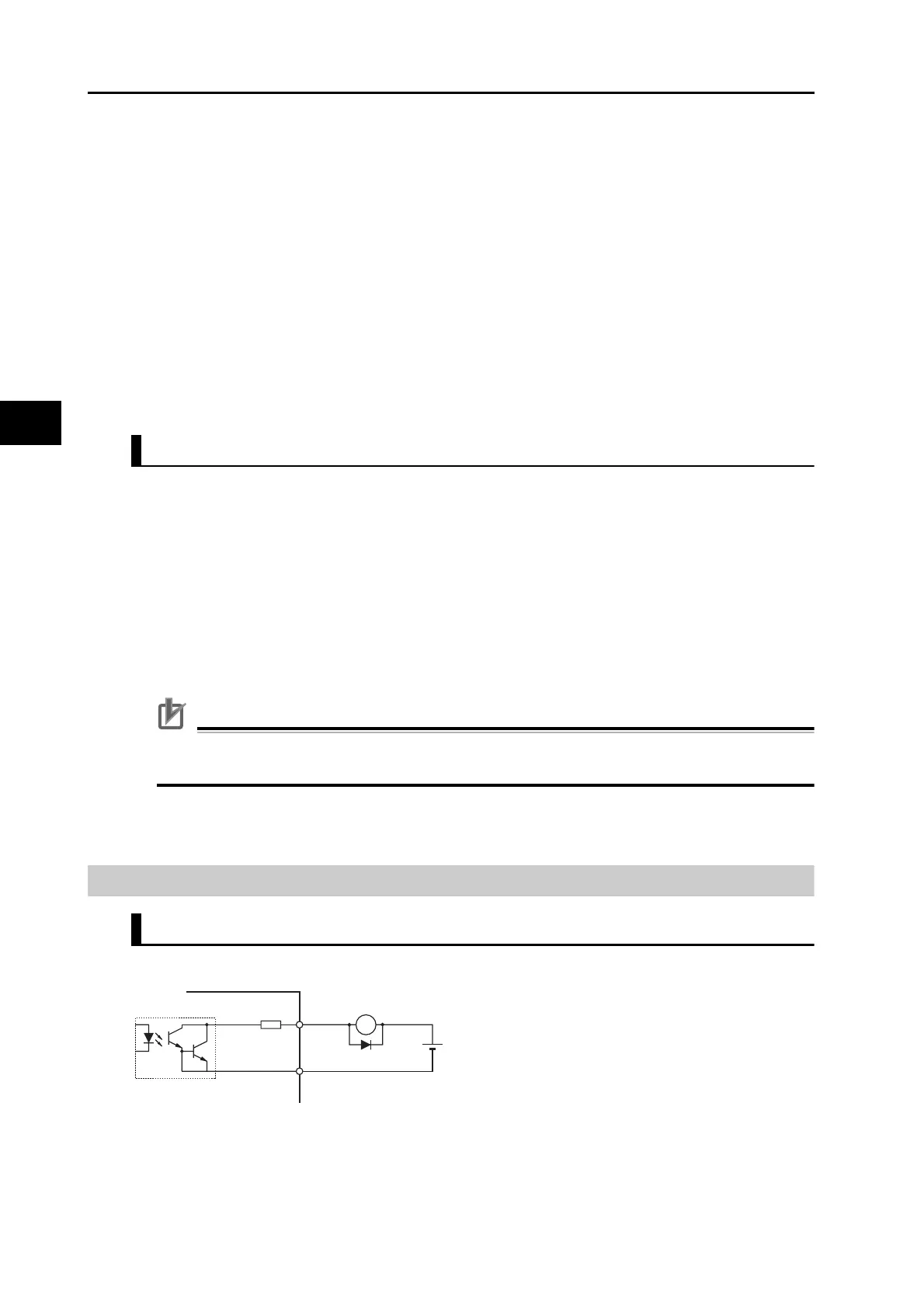
Control Output Circuits
Sequence Outputs
*1 When driving a relay directly with an output signal, always insert a diode as shown in the above figure.
Use high-speed diodes.
Pin 14: Backup Battery + Input (BAT)
Pin 15: Backup Battery − Input (BATGND)
-
X
Di
+
Di: Surge voltage prevention diode
*1
External power supply 12 to 24 VDC
Maximum service voltage: 30 VDC or less
Maximum output current: 50 mA max.
Servo Drive
10 Ω
 Loading...
