3-13
3-1 Servo Drive Specifications
OMNUC G5-series AC Servomotors and Servo Drives User’s Manual (with Built-in EtherCAT Communications)
3
Specifications
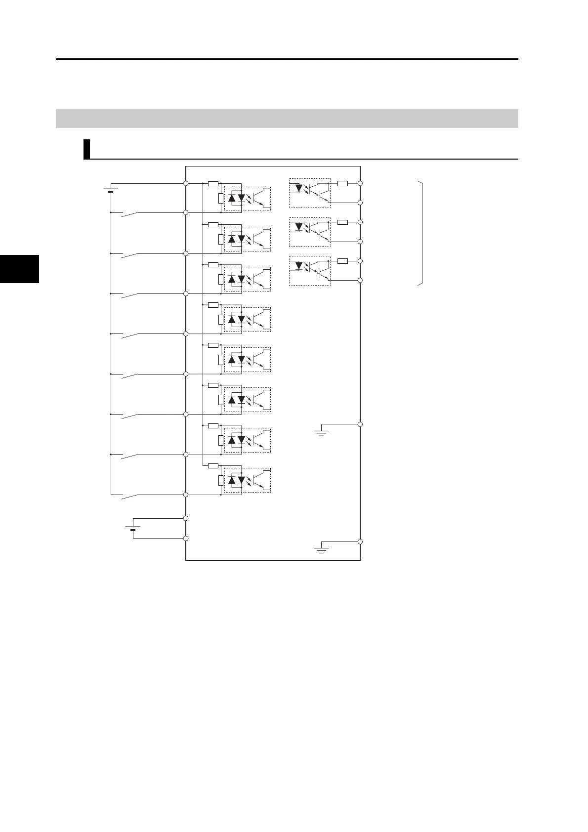
Control I/O Connector Specifications (CN1)
Control I/O Signal Connections and External Signal Processing
*1. A cable equipped with a battery is not required if a backup battery is connected.
Note 1. The input function of pins 5 and 7 to 13 are determined by object settings.
Note 2. The output function of pins 1, 2, 25 and 26 are determined by object settings.
Note 3. It is not necessary to wire input pins that are not being used.
General-purpose
input 1
/ALM
Error output
General-purpose output 1
General-purpose output 2
ALMCOM
3
4
OUTM1
OUTM1COM
OUTM2COM
1
2
OUTM225
26
12
IN7
11IN6
10IN5
9IN4
8
IN3
7
IN2
5IN1
6
+24 VIN
General-purpose
input 7
General-purpose
input 6
General-purpose
input 5
General-purpose
input 4
General-purpose
input 3
General-purpose
input 2
12 to 24 VDC
Maximum
service
voltage:
30 VDC
Maximum
output current:
50 mADC
13IN8
General-purpose
input 8
Frame ground
FG
Shell
4.7 kΩ
4.7 kΩ
4.7 kΩ
4.7 kΩ
4.7 kΩ
4.7 kΩ
4.7 kΩ
BAT
BATGND
Backup
battery
*1
14
15
1 kΩ
4.7 kΩ
1 kΩ
1 kΩ
1 kΩ
1 kΩ
1 kΩ
1 kΩ
1 kΩ
16
GND
10 Ω
10 Ω
10 Ω
 Loading...
