EasyManua.ls Logo

Omron R88D-KN20F-ECT-R User Manual

Omron R88D-KN20F-ECT-R
484 pages
To Next Page IconTo Next Page
To Previous Page IconTo Previous Page
Page #226 background imageLoading...
Page #226 background image
5-5
5-4 Process Data Objects (PDOs)
OMNUC G5-series AC Servomotors and Servo Drives User’s Manual (with Built-in EtherCAT Communications)
5
EtherCAT Communications
5-4 Process Data Objects (PDOs)
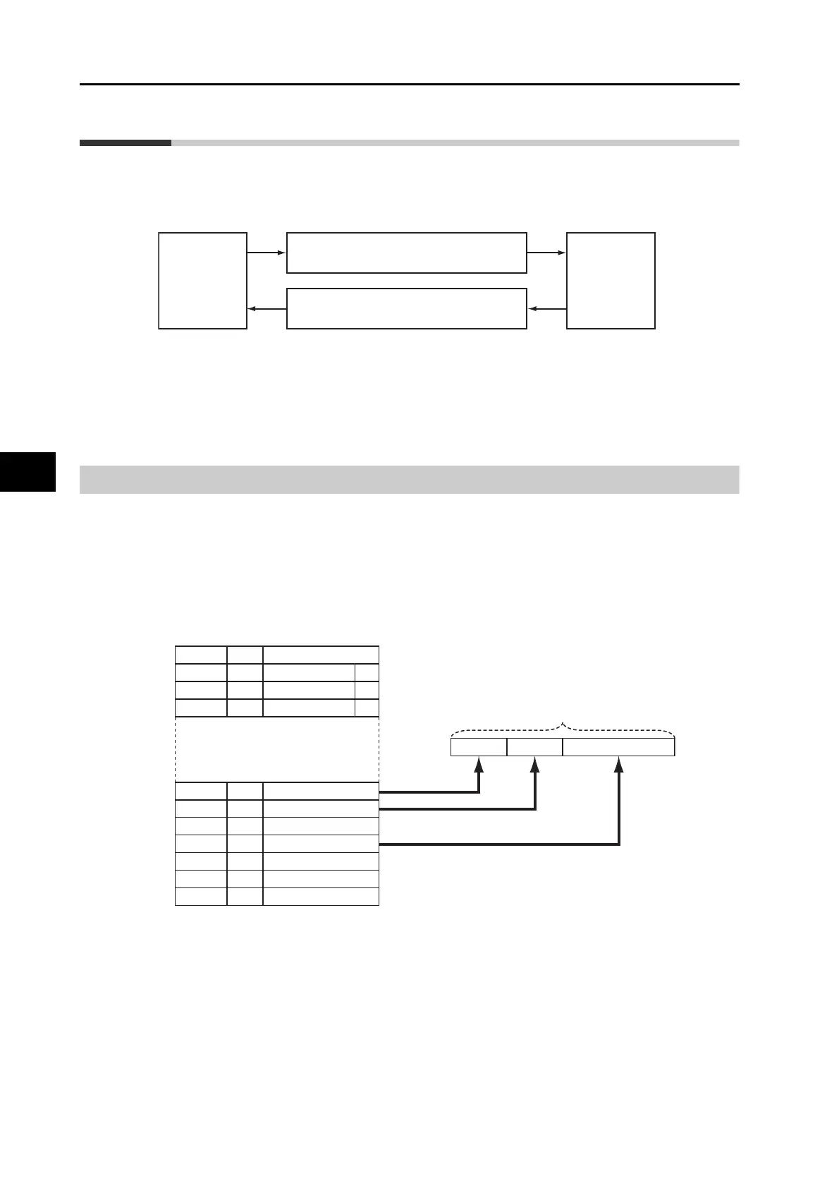
The process data objects (PDOs) are used to transfer data during cyclic communications in
realtime. PDOs can be reception PDOs (RxPDOs), which receive data from the controller, or
transmission PDOs (TxPDOs), which send status from the Servo Drive to the host controller.
The EtherCAT application layer can hold multiple objects to enable transferring Servo Drive
process data. The contents of the process data are described in the PDO Mapping object and
the Sync manager PDO assignment object.
OMNUC G5-series Servo Drives support PDO mapping for position control.
PDO Mapping Settings
The PDO mapping indicates the mapping for application objects (realtime process data)
between the object dictionary and PDO. The number of mapped objects is described in sub-
index 0 of the mapping table. In this mapping table, 1600 hex to 17FF hex are for RxPDOs and
1A00 hex to 1BFF hex are for TxPDOs.
G5-series Servo Drives use 1701 hex for RxPDOs and 1B01 hex for the TxPDOs.
The following table is an example of PDO mapping.
Host
Controller
Servo Drive
RxPDO
Operation command, target position, etc.
TxPDO
Operation status, actual position, etc
6TTTh
ZZh
Index
Sub
6UUUh UUh
16
Object contents
1ZZZh
1ZZZh
1ZZZh
01h
02h
03h
6TTTh TTh
YYYYh YYh
8
8
6UUUh
6VVVh
6YYYh
UUh
VVh
YYh
TTh Object A
Object B
6ZZZh
Object C
Object D
Object E
Application objects Mapping objects
Object Dictionary
Object A Object B Object D
PDO_1
PDO-Length: 32 bits

Table of Contents

Questions and Answers:

Omron R88D-KN20F-ECT-R Specifications

General IconGeneral
BrandOmron
ModelR88D-KN20F-ECT-R
CategoryServo Drives
LanguageEnglish

Summary

Terms and Conditions Agreement

Exclusive Warranty

Details Omron's warranty coverage for defects in materials and workmanship.

Safety Precautions

Definition of Precautionary Information

Explains the meaning of safety precautions and symbols used throughout the manual.

Precautions for Safe Use

Provides critical safety guidelines for installation, operation, and maintenance to prevent hazards.

Installation and Wiring

Details essential precautions for safe installation and wiring procedures.

Operation and Adjustment

Covers safety aspects during operation and adjustment phases.

Models and External Dimensions

2-4 External and Mounting Dimensions

Provides external dimensions and mounting dimensions for Servo Drives and Servomotors.

Specifications

3-1 Servo Drive Specifications

Provides general specifications, characteristics, and international standards for Servo Drives.

3-2 Overload Characteristics (Electronic Thermal Function)

Explains the overload protection function and provides overload characteristics graphs.

3-3 Servomotor Specifications

Details general specifications and characteristics for OMNUC G5-Series AC Servomotors.

System Design

4-1 Installation Conditions

Explains installation conditions for Servo Drives and Servomotors, including environment and mechanical connections.

4-2 Wiring

Provides wiring diagrams for peripheral equipment connection examples.

4-3 Wiring Conforming to EMC Directives

Details wiring requirements for EMC Directive conformance.

Drive Profile

6-1 Controlling the State Machine of the Servo Drive

Explains how the state of OMNUC G5-series Servo Drives is controlled via Controlword and Statusword.

6-3 Cyclic Synchronous Position Mode

Describes position control using target position and cyclic synchronization.

6-6 Fully-closed Control

Describes using an external encoder for direct position detection and feedback for accurate positioning.

Applied Functions

7-1 Sequence I/O Signals

Explains how to set sequences and allocate input/output signal functions.

7-8 Gain Switching Function

Switches position loop and speed loop gain based on conditions like load inertia or speed.

Safety Function

8-1 Safe Torque OFF Function

Explains the STO function for cutting off motor current and stopping the motor via safety device signals.

Details on Servo Parameter Objects

9-2 Gain Settings

Explains gain adjustment procedures, including automatic and manual tuning methods.

Operation

10-1 Operational Procedure

Provides a step-by-step guide for operating the motor and drive after installation and wiring.

10-2 Preparing for Operation

Details items to check before turning ON power, including supply voltage and wiring.

10-3 Trial Operation

Explains procedures for performing trial operation to confirm servo system correctness.

Adjustment Functions

11-2 Gain Adjustment

Explains gain adjustment using realtime autotuning or manual tuning for optimal responsiveness.

11-3 Realtime Autotuning

Details the automatic gain adjustment process based on machine rigidity and load inertia.

11-4 Manual Tuning

Provides procedures for manual tuning when autotuning does not achieve desired responsiveness.

Troubleshooting and Maintenance

12-1 Troubleshooting

Provides preliminary checks and analytical software for determining problem causes.

12-3 Errors

Details error output, power circuit control, and error number display on the front panel.

12-4 Troubleshooting

Guides on determining error conditions and taking appropriate measures.

Related product manuals