9-6
9-2 Gain Settings
OMNUC G5-series AC Servomotors and Servo Drives User’s Manual (with Built-in EtherCAT Communications)
9
Details on Servo Parameter Objects
9-2 Gain Settings
Refer to 11-2 Gain Adjustment on page 11-4 for the settings for gain adjustment.
Set the position loop response in accordance with the machine rigidity.
The responsiveness of the servo system is determined by the position loop gain.
Servo systems with a high position loop gain have a high responsiveness and fast positioning.
To increase the position loop gain, you must improve machine rigidity and increase the specific
damping frequency. This should be 500 to 700 (0.1/s) for ordinary machine tools, 300 to 500 (0.1/
s) for general-use and assembly machines, and 100 to 300 (0.1/s) for industrial robots. The default
position loop gain is 480 (0.1/s), so be sure to lower the set value for machines with low machine
rigidity.
Increasing the position loop gain in systems with low machine rigidity or systems with low specific
damping frequencies may cause machine resonance, resulting in an overload error.
If the position loop gain is low, you can shorten the positioning time using feed-forward.
This object is automatically changed by executing realtime autotuning. To set it manually, set the
Realtime Autotuning Mode Selection (3002 hex) to 0.
Position loop gain is generally expressed as follows:
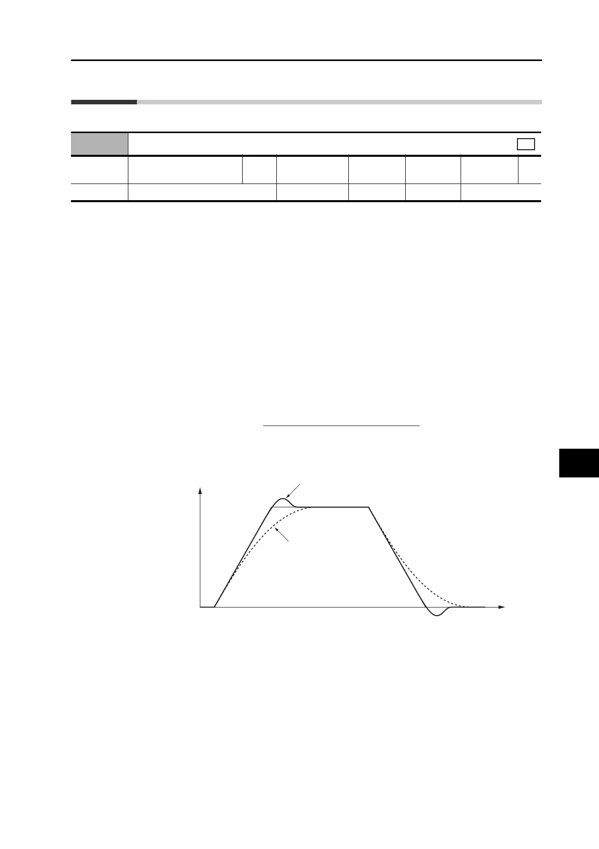
Response for Position Loop Gain Changes
3100 hex
Position Loop Gain 1
Setting
range
0 to 30000 Unit 0.1/s
Default
setting
480
*1
*1. The default setting is 320 for a Drive with 200 V and 1 kW or greater, or with 400 V.
Data
attribute
B
Size 2 bytes (INT16) Access RW PDO map Not possible.
csp
Position loop gain (Kp) =
Command pulse frequency (pulses/s)
Pulse position error (pulses)
(0.1/s)
Motor speed
Time
Position loop gain is high.
Position loop gain is low.
 Loading...
