6-15
6-6 Fully-closed Control
OMNUC G5-series AC Servomotors and Servo Drives User’s Manual (with Built-in EtherCAT Communications)
6
Drive Profile
*2 These are the directions in which the Servo Drive counts the pulses from an external
encoder with a 90° phase difference outputs.
*3 For the external encoder connection direction, set the direction so that count-up occurs
when the motor shaft is rotating counterclockwise, and count-down occurs when the motor
shaft is rotating clockwise. If the connection direction cannot be selected due to installation
conditions or any other reason, the count direction can be reversed using External
Feedback Pulse Direction Switching (3326 hex).
Precautions for Correct Use
If 3000 hex = 1, the encoder count direction becomes opposite to the count direction used for
monitoring, e.g., for the total external encoder feedback pulses.
If 3000 hex = 0, the count direction matches the count direction for monitoring.
Even when the speed command is within the Servo Drive's speed command range, an
acceleration alarm will occur if the speed command exceeds the maximum speed of the motor.
To confirm that the installation direction is correct, use the front-panel monitor or the CX-Drive
monitor function to check the counting direction of the total external encoder feedback pulses and
the total encoder feedback pulses. If the counting directions are the same, the connections are
correct.
Reference
Maximum Input Frequency
The maximum speed when an external encoder with a resolution of 0.01 µm is used for the serial
communications is 0.01 µm × (400 × 10
6
) pps = 4.00 m/s.
An overspeed error will occur, however, if the motor shaft rotation speed exceeds the maximum
speed.
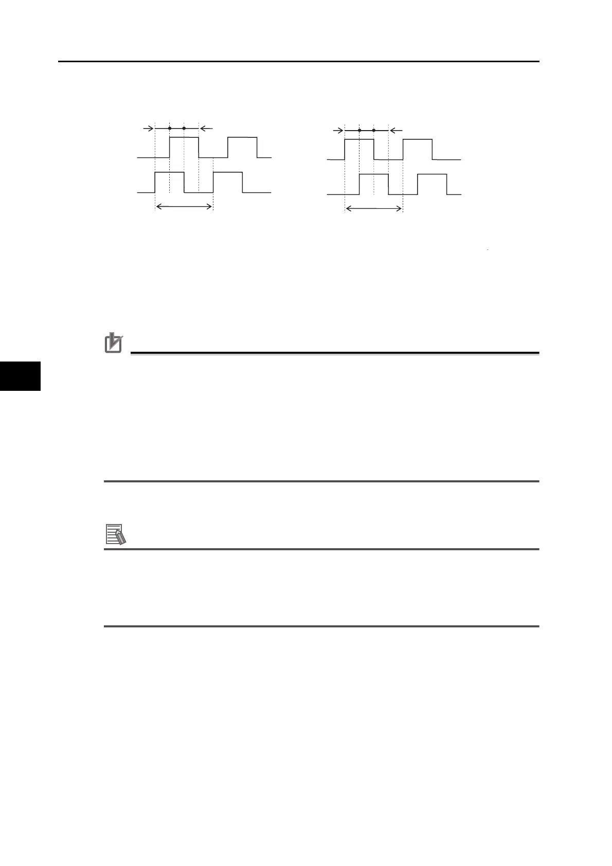
Count-down direction
EXB is 90° ahead of EXA.
t1 > 0.25 µs
t2 > 1.0 µs
EXB is 90° behind EXA.
t1 > 0.25 µs
t2 > 1.0 µs
t1
t2
t1
t2
EXA
EXB
EXA
EXB
Count-up direction
 Loading...
