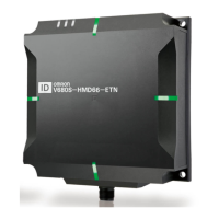
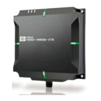
p.278
Checking the Installation Environment
Refer to Reader/Writer Installation Precautions in Section 11 Appendices to confirm the conditions under which
the RFID System will not be influenced by surrounding metal on the Reader/Writer or mutual interference
between Reader/Writers.
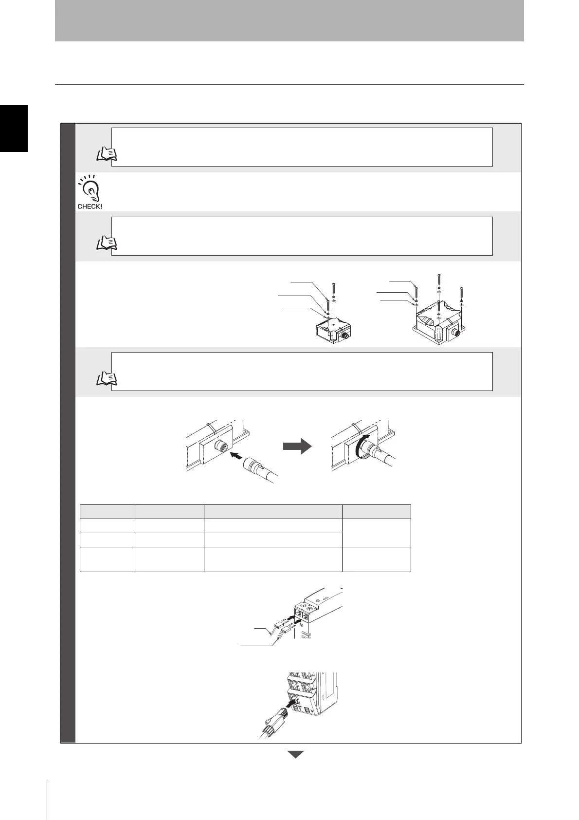
p.72
Installation
Install the Reader/Writer with four M4 screws.
V680S-HMD63-ETN: Use two screws.
V680S-HMD64-ETN/-HMD66-ETN: Use four screws.
p.87
Connections and Wiring
You must connect the power supply lines (24 VDC and 0 VDC) and the operation mode signal line in the V680S-
A41@M/-A51@M Cable.
Wire color Meaning Connected to Applicable wire
Brown 24 VDC +V DC output terminal
AWG20
Blue 0 VDC -V DC output terminal
Violet
Control signal Run Mode: +V DC output terminal
Safe Mode: -V DC output terminal*
AWG24
Note: If you start the Reader/Writer with the control signal connected to the -VDC side of the power supply, the Reader/Writer
will start in Safe Mode.
Insert the V680S-A41@M/-A51@M Cable into the connector on the Reader/Writer and turn the cable connector on
the Reader/Writer end clockwise to lock it in place.
Connect the RJ45 connector on the V680S-A41@M/-A51@M Cable to an Ethernet port on the host device.
* Connect the RJ45 connector to the Switching Hub when you use Switching Hub.
Preparations
 Loading...