90
Section 4 Connections and Wiring
RFID System
User's Manual
(Modbus TCP)
Section 4
Installation and Connections
Connecting the V680S-A41
@
M/-A51
@
M Cable to the Host Device
Power Supply and Operation Mode Signal
You must connect the power supply lines (24 VDC and 0 VDC) and the operation mode signal line in
the V680S-A41@M/-A51@M Cable.
Refer to Safe Mode in Section 9 Troubleshooting for information on Safe Mode.
p.262
Connect the three terminals correctly. Otherwise, the Reader/Writer may be damaged.
Power Supply
Use a power source that meets the following conditions.
Conditions
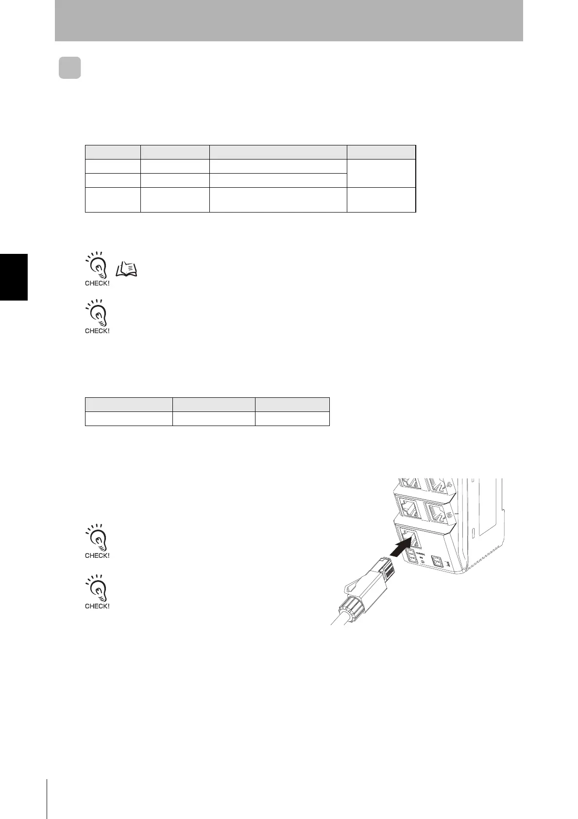
Connecting the Host Device
Connect the RJ45 connector on the V680S-
A41@M/-A51@M Cable to an Ethernet port on the
host device.
Press in the connector until it locks into place.
Use a device supporting STP cables for the host
device (such as a Switching Hub or PLC) which is
connected the specified Cables (V680S-A41 @M/-
A51 @M). Ground the host device to a ground
resistance of 100 Ω or less.
Wire color Meaning Connected to Applicable wire
Brown 24 VDC +V DC output terminal
AWG20
Blue 0 VDC -V DC output terminal
Violet
Control signal Run Mode: +V DC output terminal
Safe Mode: -V DC output terminal*
AWG24
Note: If you start the Reader/Writer with the control signal connected to the -VDC side of the
power supply, the Reader/Writer will start in Safe Mode.
Power supply voltage Output current Safety directive
24 VDC -15% to +10% 500 mA DC or higher UL Class 2
 Loading...