Section 4 Connections and Wiring
Section 4
Installation and Connections
RFID System
User's Manual
(Modbus TCP)
89
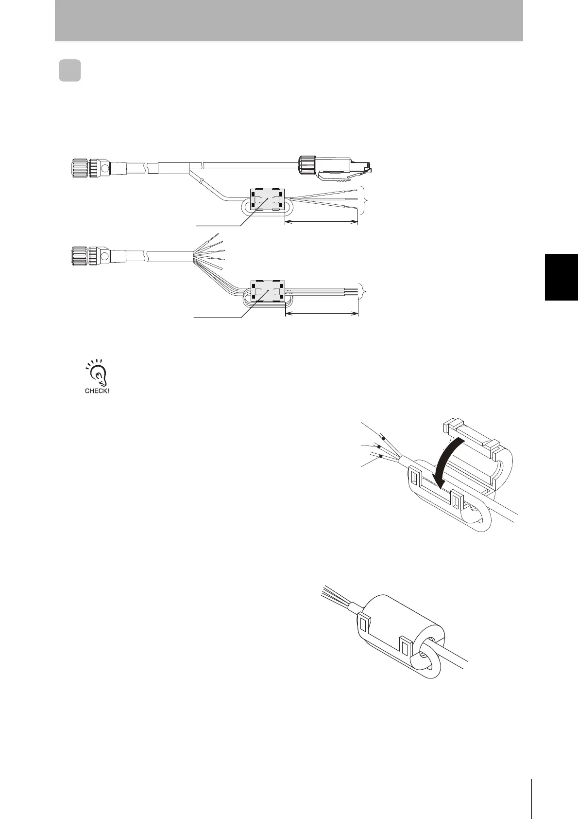
Attaching Ferrite Core
If you use the V680S-HMD66-ETN, attach the ferrite core that is provided with the Reader/Writer to the
V680S-A41M/-A42M/-A51M Cable.
You do not need to attach a V680S-A40M/-A50M Extension Cable.
V680S-A4 is a standard cable. The wire color is gray.
V680S-A5 is a robot instrumentation cable. The wire color is black.
1. Wrap the power supply lines and Control
signal line together around the ferrite core
once. The ferrite core should be within 5cm
from the tip of the cable.
2. Close the ferrite core until you hear it click
into place.
5cm
Ferrite core
5cm
Ferrite core
Power supply lines: Brown (+24V),Blue(0V)
Control signal line: Purple
Power supply lines: Brown (+24V),Blue(0V)
Control signal line: Purple
V680S-A41 / -A51
V680S-A42
Power supply line: +24V
(Brown)
Power supply line: 0V
(Blue)
Control signal line
(Purple)
 Loading...