92
Section 4 Connections and Wiring
RFID System
User's Manual
(Modbus TCP)
Section 4
Installation and Connections
Assembling and Connecting the V680S-A42
@
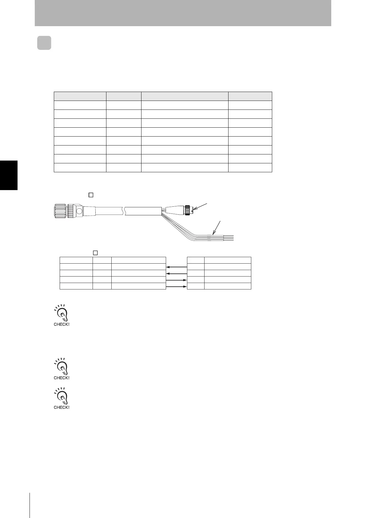
M Cable and Connector
Assembly Method
Follow the table below, assemble the connector.
Prepare the shielded-connectors according to the application.
Example Connection
Following the instructions of the manufacturer of the connector, ground connecting the FG with the connector side.
Connecting the Host Device
Connect the connector on the V680S-A42@M Cable to an Ethernet port on the host device.
The Reader/Writer supports for Auto-MDIX, can communicate by both straight and cross ethernet lines.
Use a device supporting STP cables for the host device (such as an Ethernet switch or PLC) which is connected the
specified Cables (V680S-A42 @M). Ground the host device to a ground resistance of 100 Ω or less.
Wire color Name Function Applicable wire
Brown 24P +24V AWG20
(Drain wire) FG Frame ground ---
Purple CONT Control signal AWG24
Orange TD- Ethernet send data - AWG24
Green/White(stripe) RD+ Ethernet receive data + AWG24
Orange/White(stripe) TD+ Ethernet send data + AWG24
Blue 24N 0V AWG20
Green RD- Ethernet receive data - AWG24
Name
TXP
TXN
RXP
RXN
FunctionName
TD+
TD-
RD+
RD-
Wire color
Orange/White
Orange
Green/White
Green
M12 Connector
V680S-A42 M
Transmitted data (+)
Transmitted data (-)
Received data (+)
Received (-)
Function
Ethernet send data +
Ethernet send data -
Ethernet receive data +
Ethernet receive data -
M12 Connector
Power supply lines, Control signal line
V680S-A42 M
 Loading...