Base Module Installation
3-2 StorageTek SL150 Modular Tape Library Installation Manual
5-ClipNut
The accessory package for the module contains parts needed to complete the
installation (such as the back rail pieces, screws, clip nuts, and mounting blocks).
After securing the base module in the rack, you can add one or more modules to
expand cartridge capacity and increase the number of tape drives. The tape drive
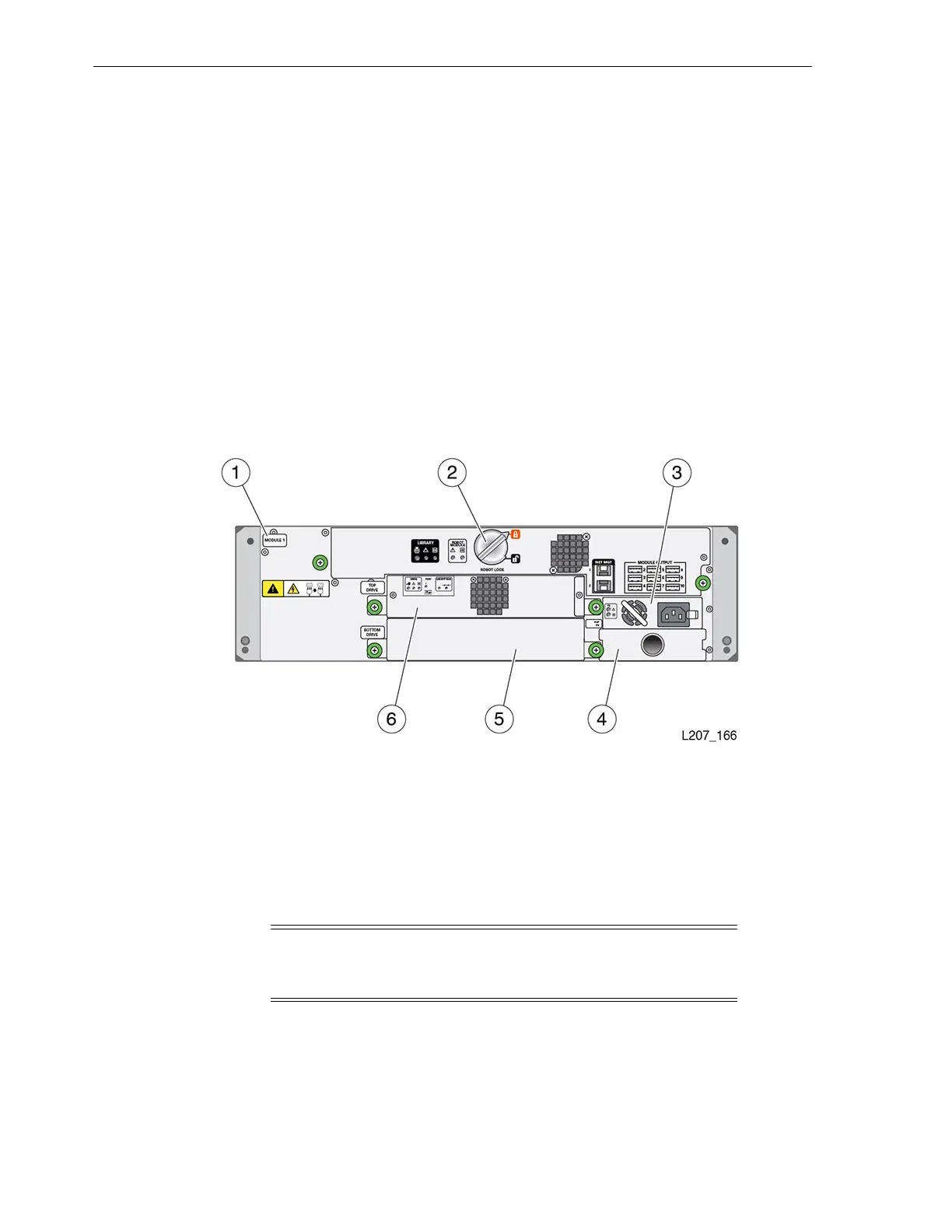
assemblies and power supplies are located at the back of a module (see Figure 3–2).
The robot CRU is located at the top of the base module. The robot is locked in the
retracted position during shipment (see Figure 3–2). You must reset the robot lock
during the initial installation process. To add modules after the initial library
installation, you must park the robot and lock it in the shipping position before
installation of an expansion module.
Each module is identified by a label in the rear, upper–left corner (Module 1 in
Figure 3–2). The first expansion module is identified as Module 2. The identification
label for an expansion module is attached during the installation process.
Figure 3–2 Rear View of the Base Module (Identified as Module 1)
Illustration Legend:
1 - Module Label
2 - Robot Lock (Improved Design)
3 - Power Supply
4 - Power Supply Filler
5 - Tape Drive Filler
6 - Tape Drive Assembly
Base Module Installation
The following tasks are performed to install the base module:
1. Prepare the rack (see "Rack Preparation").
Note: The installation instructions in this guide are based upon
the Sun Rack II. If your rack is different (M5 or M6 holes), use the
instructions as a basic guide but alter steps accordingly.
 Loading...