2
Rack Mount Controls and Indicators 2-1
2
Rack Mount Controls and Indicators
This chapter provides information about the indicators and switches located on the
rack mount drive.
Front Panel
The T10000 Tape Drive rack mount configuration chassis contains one or two drives.
The chassis front panel (Figure 2–1) provides manual loading or unloading of tape
cartridges into each drive through separate cartridge slots. The front panel also has a
dual operator panel mounted between the cartridge slots. The upper portion is for
drive A (left), and the lower portion is for drive B (right).
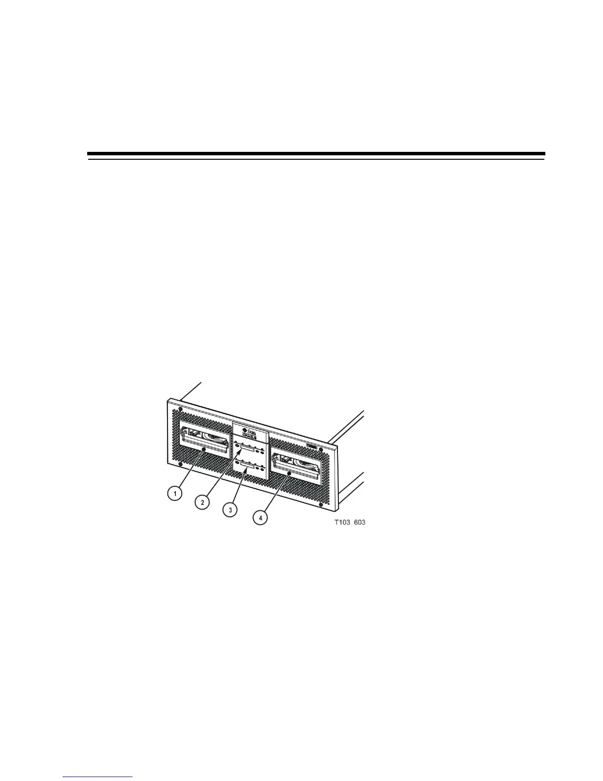
Figure 2–1 Rack Mount Chassis Front Panel
Illustration Legend:
1 - Cartridge slot drive A
2 - Operator panel drive A
3 - Operator panel drive B
4 - Cartridge slot drive B
Load/Unload Slot
The cartridge slots accept only StorageTek T10000 or StorageTek T10000 T2 tape
cartridges. All other cartridge types will not load into the T10000 tape drive. After you
have inserted a tape cartridge, the loader mechanism lowers the cartridge onto the hub
motor, and threads the tape.
 Loading...