Rear Panel
2-4 StorageTek T10000 Tape Drive Operator’s Guide
■ Menu selections and configuration choices
■ Error messages and fault symptom codes
■ Host-generated messages
The display window is formed by a horizontal row of ten array segments. Each
segment is an array of 35 dots—five wide and seven high. Each array can form an
uppercase or lowercase alpha character, a numeral, or a special character (such as an
asterisk [*]).
Multiple messages or a message greater than ten characters are displayed by the
window, alternating between required character groups.
Note: Appendix D lists messages that could appear in the display
window.
Rear Panel
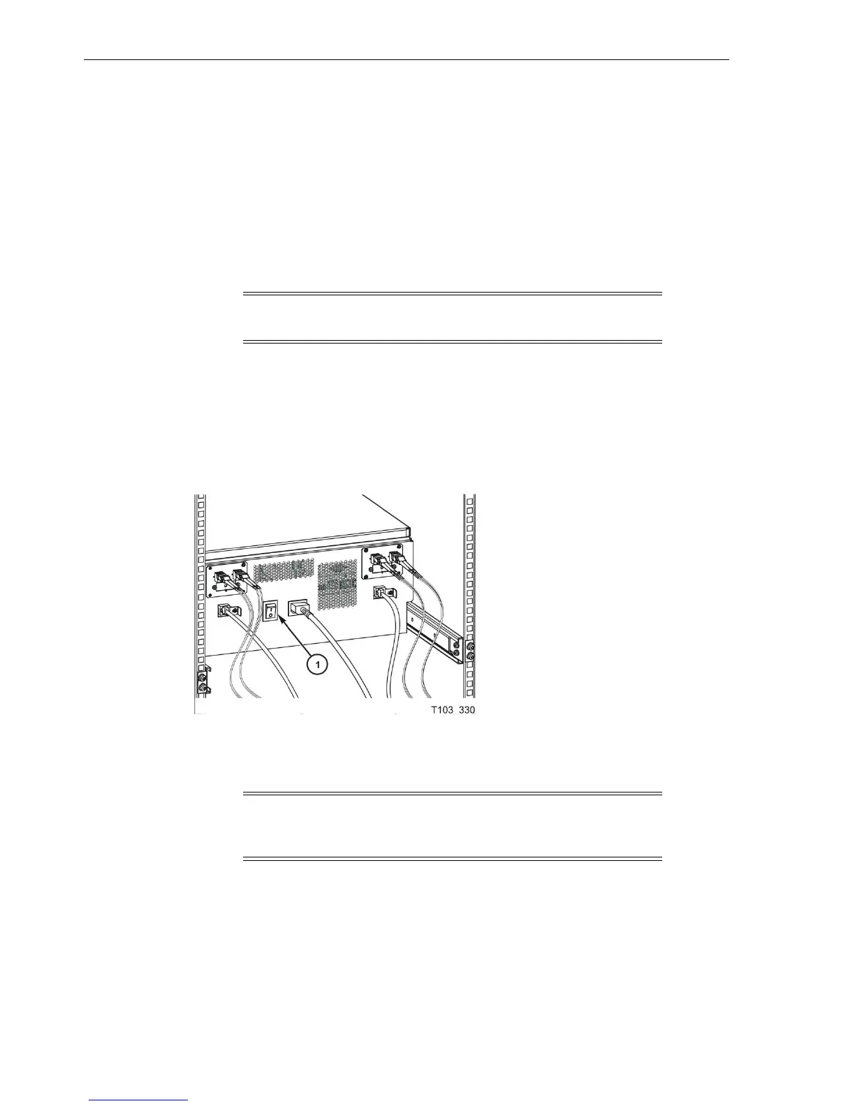
Figure 2–3 shows the rear of the rack mount chassis. One AC power connector and one
AC switch supplies AC power to both drive power supplies, which are mounted
internally, between the drives.
Figure 2–3 Rack Mount Chassis Rear Panel
Illustration Legend:
1 - AC power switch
Note: The drive status indicator and encryption status indicator,
for encryption-capable drives, are visible through the drive cooling
grids (does not apply to the T10000D tape drive).
 Loading...