Design Guide for the Polycom SoundStructure C16, C12, C8, and SR12
9 - 18
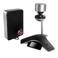
The logic inputs will have a default value of 1 (high) when the contact closure
is open, and will have a value of 0 (low) when the contact closure is closed and
tied to ground.
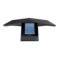
A typical contact closure example is shown in the following two figures. In the
first figure, the input generates the value 1 (high) because the switch is open.
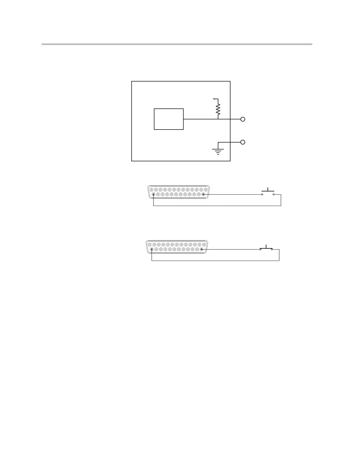
When the logic switch is closed, as shown in the figure below, the logic value
will read the value 0 (low) indicating that the contact has been closed.
The logic inputs are internally debounced and can detect changes in the con-
tact closures as short as 100msec.
Analog Logic Inputs
The analog gain inputs (analog gain 1 and 2) operate by measuring an analog
voltage between the analog input pin and the ground pin. The maximum
input voltage level should not exceed +6 V. It is recommended that the +5 V
supply on Pin 1 be used as the upper voltage limit.
An example of connecting a volume knob potentiometer for volume control is
shown in the following figure. In this figure the volume knob will have three
connections – one to the +5V connection, one to ground, and the third, the
wiper of the potentiometer, will be connected to the analog gain input. As the
Logic
Status
SoundStructure Logic Input
Logic Input Pin
Logic Pin 25 (Ground)
3.3V
Remote Control
Pin 14 : Logic Input 1
Pin 25 : Ground
Remote Control
Pin 14 : Logic Input 1
Pin 25 : Ground